


Edition 3
Rev G
Appendix E
E-3
See Note:
SPAN
mV
0/10000
0/1000
0/100
0/25
See Note:
SPAN
mA
4/20
0/20
5
DEVIATION
ACC'Y
uV/°C
1000
100.0
10.0
2.5
5
DEVIATION
ACC'Y
uA/°C
2.0
2.0
6
RESOL
uV/bit
381
38.1
3.81
0.954
6
RESOL.
uA/bit
0.763
0.763
4
REF+LIN
+CAL
uV
3500
350
45
26
4
REF+CAL
uA
7
7
3
FACTORY
CAL
uV
1000
100
20
20
3
FACTORY
CAL
uA
2
2
1
REF
ACC'Y
uV
2500
250
25
6
1
REF.
ACC'Y
uA
5
5
LINEAR
RANGES
10V
1V
100mV
25mV
LINEAR
RANGES
mA
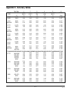
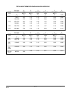
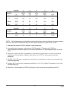
NOTES: The Table attempts to show the effect of each significant factor which contributes to the overall measure-
ment error. See the enumerated items below for more specific explainations of each column of data.
1. Reference Acc'y based on 0.025% (250ppm) of input voltage span.
2. Linearization Acc'y is based on conformance to NIST Monograph 175 (based on the ITS-90) for
letter-designated thermocouple types, or other industry standards for non letter-designated type T/Cs and all
RTDs.
3. Factory Cal is defined by limits of repeatability in a manufacturing environment of ±10uV for zero and span
calibrations on thermocouples, as stated or other inputs, and ±0.15°C for thermocouple cold junction
calibrations.
4. The REF + LIN + CAL column represents the total "static" error allowed for an instrument as produced by the
manufacturing process.
5. Deviation Acc'y is derived from a temperature coefficient of .01%/°C or ±100ppm/°C expressed in units of the
corresponding range.
6. Resolution on thermocouples and RTDs is derived as a function of the input voltage Range and dV/dT.