


Section 2
2-16
Edition 3
Rev G
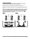
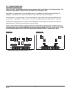
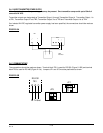
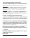
2.4.4 24VDC TRANSMITTER POWER SUPPLY
Note: Up to four transmitter power supplies may be present. One transmitter can provide up to 25mA of
current at 24 VDC.
Transmitter outputs are designated as Transmitter Output 1 through Transmitter Output 4. Transmitter Output 1 is
at TB1, Transmitter Output 2 is at TB2, Transmitter Output 3 is at TB3 and Transmitter Output 4 is at TB4.
If an isolated 24 VDC regulated transmitter power supply has been specified, the connections should be made as
shown.
FIGURE 2-15A
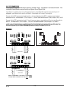
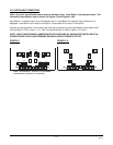
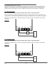
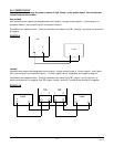
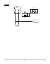
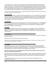
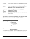
2.4.5 COMMUNICATIONS
The connections should be made as shown: Terminal block TB1 is used for RS-232 (Figure 2-15B) and terminal
block TB3 is used for RS-485 (Figure 2-15c). Jumpers JP1 and JP3 must be positioned as shown.
FIGURE 2-15B
TBX
12
+
-
+
-
+
-
12
INPUT
2 Wire
Transmitter
Rx
Tx
Grnd
RS-232
TB1
JP3
JP1