


Section 2
2-10
Edition 3
Rev G
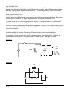
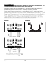
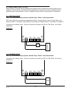
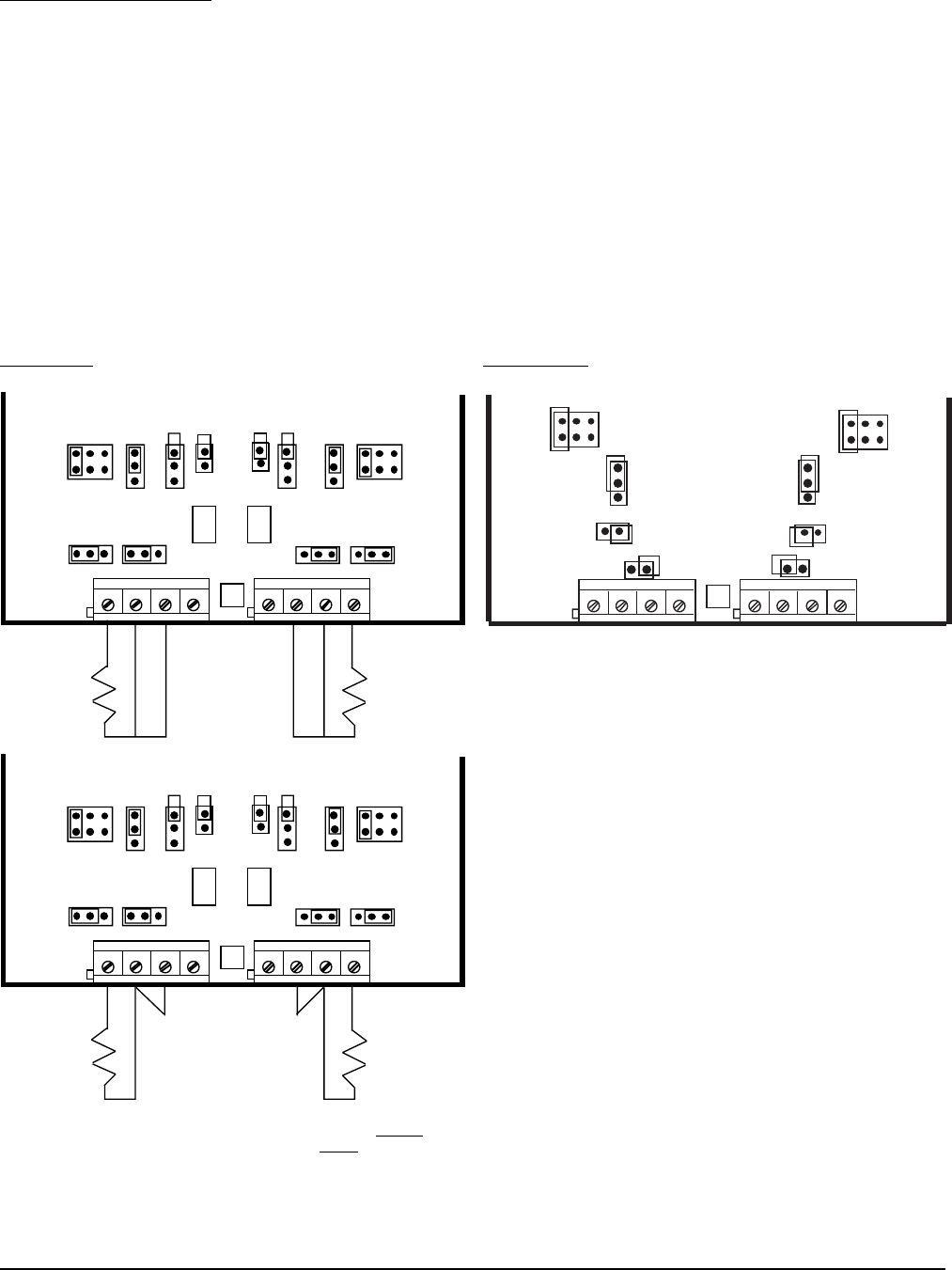
2.3.5 RTD CONNECTIONS
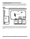
Note: Up to four Input Boards may be present; stacked 4 high. Input Board 1 is the bottom board. Two
versions of Input Board s may be found, see Figure 2-8 and Figure 2-8A.
Input Board 1 is used for Input 1 and, if equipped, Input 2. Input Board 2 is used for Input 3 and Input 4, if
equipped. Input Board 3 is for Input 5 and Input 6. Input Board 4 is for Input 7 and Input 8.
Connect 2 wire RTD inputs to terminals 3 and 4 on the Input Board(s) to be RTD. Install a jumper between
terminals 2 and 3. Terminal block 1 (TB1) is Input 1, 3, 5 and 7 and terminal block 2 (TB2) is Input 2, 4, 6, and 8.
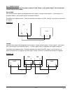
Connect 3 wire RTD inputs to terminals 2, 3 and 4 (common legs on terminals 2 and 3) on the Input Board(s) to
be RTD. Terminal block 1 (TB1) is Input 1, 3, 5, and 7 and terminal block 2 (TB2) is Input 2, 4, 6, and 8.
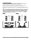
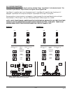
NOTE: INPUT CONDITIONING JUMPERS MUST BE POSITIONED AS SHOWN FOR AN RTD INPUT IN
EITHER FIGURE 2-8 OR 2-8A DEPENDING ON WHICH CIRCUIT BOARD IS FITTED.
FIGURE 2-8 FIGURE 2-8A
JU3 JU1
JU11
U6
JU7
++--
11
TB1
TB2
JU2
JU5 JU12
JU4 JU6
JU8
JU15 JU16
3 WIRE RTD
JU3 JU1
JU11
U6
JU7
++--
11
TB1
TB2
JU2
JU5 JU12
JU4 JU6
JU8
JU15 JU16
JUMPER
(Customer Supplied)
2 WIRE RTD
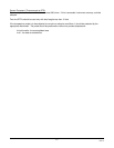
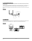
NOTE: Terminal Block 1, Terminal 1 is on the RIGHT,
Terminal Block 2, Terminal 1 is on the
LEFT.
U1
++--
11
TB1
TB2
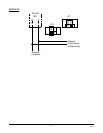
JU5
JU6
JU16
JU7
JU3
JU2
JU15
JU8