


Section 2
2-15
Edition 3
Rev G
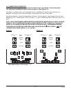
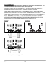
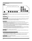
2.4.3 CURRENT OUTPUT
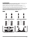
Note: Up to two boards may be present, stacked 2 high. Board 1 is the bottom board. Non-isolated and
isolated outputs are available.
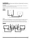
Non-isolated
Non-isolated current outputs are designated as current output 1 through current output 2. Current output 1 is
located on Board 1 and Current Output 2 is located on Board 2.
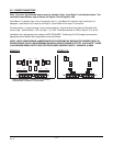
Connections are made as shown. Terminal connections are made using TB1, terminal 1 is positive and terminal 2
is negative.
FIGURE 2-14
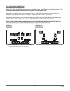
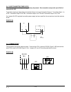
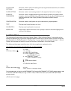
Isolated
Isolated current outputs are designated current output 1 through current output 4. Current output 1, and if speci-
fied, current output 2, are located on board 1. Current outputs 3 and 4, if specified, are located on board 2.
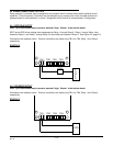
Connections are made as shown. Terminal connections are made using TB1 (output 1 and 3), terminal 1 is
positive and terminal 2 is negative, and TB2 (output 2 and 4), terminal 1 is positive and terminal 2 is negative.
FIGURE 2-14B
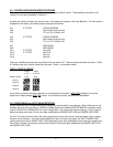
TB1
12
+
-
LOAD
+
-
Load
+ -
TB1 TB2
1 2 1 2
+ - + -
Load
+ -