


Section 2
2-14
Edition 3
Rev G
1
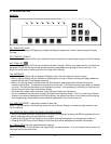
TB1 TB2 TB3 TB4
SSR
+
-
+-
N
O
TB1 TB2 TB3 TB4
P
O
W
E
R
N
C
C
LOAD
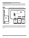
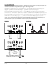
2.4 WIRING CONNECTIONS - OUTPUTS
Relay output(s), if provided, may be assigned to any actuator, which includes alarms and/or optional control
capability. Current output(s), if provided, may be assigned to any analog value, which includes derived and
process values for retransmission or control. Assignment of the function is accomplished in Configuration.
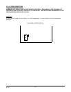
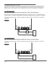
2.4.1 SPDT RELAY OUTPUT
Note: Up to two Boards may be present; stacked 2 high. Board 1 is the bottom board.
SPDT and/or SSR driver outputs is/are designated as Relay 1 through Relay 8. Relay 1 through Relay 4 are
located on Board 1 and Relay 5 through Relay 8 (if provided) are located on Board 2. See Figure 2-4, page 2-6.
Connections are made as shown. Terminal connections are made using TB1 thru TB4, Relay 1 thru Relay 4
respectively.
FIGURE 2-12
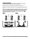
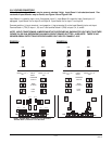
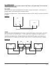
2.4.2 SSR DRIVER OUTPUT
Note: Up to two Boards may be present; stacked 2 high. Board 1 is the bottom board.
Connections are made as shown. Terminal connections are made using TB1 thru TB4, Relay 1 thru Relay 4
respectively.
FIGURE 2-13