Appendix DEdition 3
Rev G
D-2
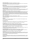
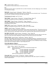
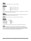
EXAMPLE 2
Application:
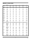
User would like to combine logically 3 alarms to create an AND situation.
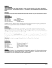
Configuration:
Derived Actuators:
Derived Actuator 1
DA1 Item 1 A11 (Alarm 1 Process Value 1 Active)
DA1 Item 2 AND
DA1 Item 3 A12 (Alarm 2 Process Value 1 Active)
DA1 Item 4 AND
DA1 Item 5 A13 (Alarm 3 Process Value 1 Active)
DA1 Item 6 END
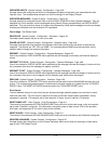
If Alarm 1 on Process Value 1 is Active AND Alarm 2 on Process Value 1 is Active AND Alarm 3 on Process Value
1 is Active, THEN DA1 (Derived Actuator 1) will be TRUE.
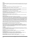
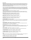
EXAMPLE 3
Operator Inputs
Operator Inputs are prompts the end user may program into the instrument that allow these prompts to turn on or
off actuators that control some other function within the instrument.
Application:
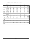
A user would like to turn an exhaust fan on or off as required by an operator via the keypad.
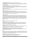
Configuration:
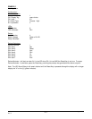
Operator Inputs:
Operator Input 1
OI1 Prompt Text EXHAUST FAN
OI1 Off/No/0 Choice FAN OFF
OI1 On/Yes/1 Choice FAN ON
OI1 Actuation Style CONTINUOUS
OI1 Power Up State SAME
OI1 When Displayed ALWAYS
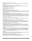
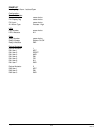
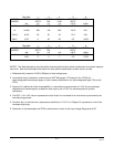
To complete configuring, configure Relay X Actuator OP INP 1 and connect Relay X to the exhaust fan.
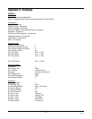
Operation:
From the Normal Display, depress the DISP key until EXHAUST FAN appears in the top display line and
FAN OFF FAN ON appears in the bottom display line, one of these should be blinking indicating the current
state of the fan. Depress the key located directly below the choice that is not blinking (F1 FAN OFF & F5 FAN
ON). IF FAN ON was selected, a relay should energize corresponding to the relay assigned above. If FAN OFF
was selected, a relay should de-energize corresponding to the relay assigned above.


