


Edition 3
Rev G
Section 3
3-11
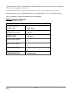
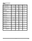
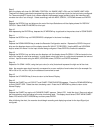
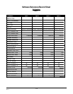
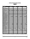
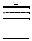
TABLE 3-2 Recorder Parameters
(Not all parameters are shown)
RECORDER NUMBER 1 2 3 4
Rs RECORDER TAG
t t t t t t t t t t t t t t t t t t t t FLOW #1 TEMP #1 PH #1 ALARM #1
Rs VALUE TO RECORD
(VALUE) DV1 IV2 IV4 DV2
Rs PEN/COLOR
(PEN/COLOR) BLUE GREEN BLACK RED
RS CHART DIVISIONS
n n n 100 100 100 100
Rs ZONE 1 LOW
DIVISION n n n 0 0 30 70
Rs ZONE 1 HIGH
DIVISION n n n 100 10 100 80
Rs SPAN 1 LOW
n n n n n n n u u u u u u 0 GPM 20 F 0 PH 0
Rs SPAN 1 HIGH
n n n n n n n u u u u u u 400 GPM 120 F 14 PH 1
Rs SCALE 1 INTERVAL
n n DIVISIONS 10 10 10 10
Rs ZONE 2 HIGH
DIVISION n n n 0 100 0 0
Rs SPAN 2 HIGH
n n n n n n n u u u u u u N/A 210 F N/A N/A
Rs SCALE 2 INTERVAL
n n DIVISIONS N/A 10 N/A N/A
Rs POSITION ON ERROR
DIVISION n n n 100 100 20 90