


Appendix DEdition 3
Rev G
D-4
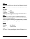
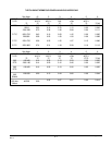
EXAMPLE 6
Latching Alarm
Configuration:
Process Variables:
Process Variable 1
PV1 Display Tag users choice
PV1 Input IV1
A11 Alarm Type Process - High
A11 Hysteresis 3
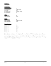
LEDs:
LED Number 8
LED 8 Actuator DA1
Relays:
Relay Number 4
Relay 4 Usage State or On-Off
Relay 4 Actuator DA1
Derived Actuators:
Derived Actuator 1
DA1 Item 1 Not
DA1 Item 2 Reset
DA1 Item 3 And
DA1 Item 4 DA1
DA1 Item 5 Or
DA1 Item 6 A11
DA1 Item 7 End
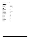
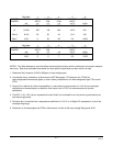
Derived Actuator 1 will be true when A11 is true OR when DA 1 is true AND the Reset Key is not true. To cause
Derived Actuator 1 to be false, press the Reset key, providing the process has gone below the alarm set point.
Note: The LED 8 and Relay 4 will remain latched until the Reset Key is pressed although the display will no longer
display the "H" or the "g" (global indicator).