


Edition 3
Rev G
Section 11
11-3
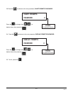
Step 4
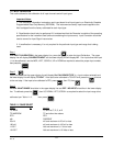
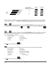
Be sure that the jumpers on the Input Board for the Input being calibrated are positioned as shown in Table 11-3,
and Figure 11-1 or Table 11-3A and Figure 11-1A, depending on which circuit board is fitted.
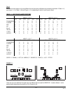
TABLE 11-3 INPUT BOARD JUMPER POSITIONS
INPUT 1, 3, 5, 7 INPUT 2, 4, 6, 8
JU1 JU2 JU3 JU7 JU11 JU15 JU4 JU5 JU6 JU8 JU12 JU16
TC NARROW U L P R R P U R P R L P
TC WIDE U L P M R P U R P M L P
RTD PLULLPPRULRP
mA ULPL RUURPLL U
25 mV ULPRRPURPRLP
100 mV U L P M R P U R P M L P
1 VOLT ULPLRPURPLLP
10 VOLT ULDLRPURDLLP
INPUT 1, 3, 5, 7 INPUT 2, 4, 6, 8
JU2 JU3 JU7 JU15 JU5 JU6 JU8 JU16
TC NARROW P P R P P P R P
TC WIDE P P M P P P M P
RTD PUL P PULP
mA PPLF PPLF
25 mV P P R P P P R P
100 mV P P M P P P M P
1 VOLT P P P L P P P L P
10 VOLT P D L P P D L P
CODE: D - DOWN, L - LEFT, M - MIDDLE, P - PARKED, R - RIGHT, U - UP, F - FITTED
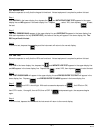
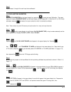
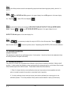
FIGURE 11-1
There are up to an additional 2 jumpers per Input Board that are used for BOARD ID. Location (Board 1 is the
bottom board) determines the position of JU13 and/or JU14.
JU3 JU1
JU11
U6
JU7
++--
11
TB1
TB2
JU2
JU5 JU12
JU4 JU6
JU8
JU15 JU16
U1
++--
11
TB1
TB2
JU5
JU6
JU16
JU7
JU3
JU2
JU15
JU8