


23
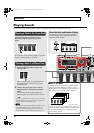
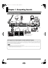
Chapter 1 Outputting Sounds
Chapter
1
•
To prevent malfunction and/or damage to speakers or other devices,
always turn down the volume, and turn off the power on all devices
before making any connections.
• Raise the amp volume only after turning on the power to all connected
devices.
• When connection cables with resistors are used, the volume level of
equipment connected to the INPUT jack may be low. If this happens,
use connection cables that do not contain resistors.
• When outputting in mono, connect the cable to the OUTPUT L/MONO
jack.
• Use only the specified expression pedal (Roland EV-5 or BOSS FV-500L;
sold separately). By connecting any other expression pedals, you risk
causing malfunction and/or damage to the unit.
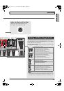
• Depending on the circumstances of a particular setup, you may
experience a discomforting sensation, or perceive that the
surface feels gritty to the touch when you touch this device,
microphones connected to it, or the metal portions of other
objects, such as basses. This is due to an infinitesimal electrical
charge, which is absolutely harmless. However, if you are concerned
about this, connect the ground terminal (see figure) with an external
ground. When the unit is grounded, a slight hum may occur, depending
on the particulars of your installation. If you are unsure of the
connection method, contact the nearest Roland Service Center, or an
authorized Roland distributor, as listed on the “Information” page.
Unsuitable places for connection
· Water pipes (may result in shock or electrocution)
· Gas pipes (may result in fire or explosion)
· Telephone-line ground or lightning rod
(may be dangerous in the event of lightning)
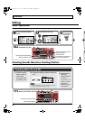
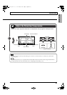
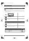
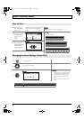
• Place the AC adaptor so the side with the indicator (see illustration) faces
upwards and the side with textual information faces downwards.
The indicator will light when you plug the AC adaptor into an AC outlet.
• To prevent the inadvertent disruption of power to your unit (should the
plug be pulled out accidentally), and to avoid applying undue stress to
the AC adaptor jack, anchor the power cord using the cord hook, as
shown in the illustration.
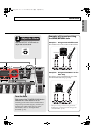
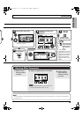
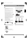
• This instrument is equipped with balanced (XLR) type connectors.
Wiring diagrams for these connectors are shown below. Make
connections after first checking the wiring diagrams of other equipment
you intend to connect.
• When connecting an expression pedal to the EXP PEDAL2/CTL 3,4 jack, set the
minimum volume for the connected expression pedal to the “MIN” position.
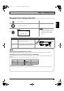
• When connecting a BOSS FS-6 footswitch (optional) to the EXP PEDAL 2/CTL
3,4 jack, set the MODE switch and POLARITY switch as shown below.
• When connecting a BOSS FS-5U footswitch (optional) to the EXP
PEDAL 2/CTL 3,4 jack, set the POLARITY switch as shown below.
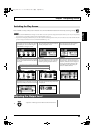
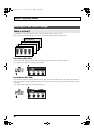
• You can use the special (optional Roland) PCS-31 connector cord to
connect two footswitches.
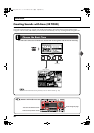
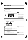
• When a BOSS FS-6 footswitch (optional) is connected to the CTL3,4 jack
with an optional connection cable (stereo 1/4” phone – stereo 1/4” phone),
pedal switch B operates according to the CONTROL 3 settings, and pedal
switch A operates according to the CONTROL 4 settings.
•
When using the unit with an expression pedal or a footswitch (the optional
FS-6 or FS-5U) connected to the EXP PEDAL 2/CTL 3,4 jack, make the
settings given on “Using Pedals to Control the Parameters” (p. 48).
• For more on using the AMP CONTROL jack, refer to “AMP CONTROL”
(p. 132).
Indicator
AC Outlet
Power Cord
AC Adaptor
BOSS FS-6
BA
Porarity Switch
PCS-31 cable
To CTL3,4 jack To CTL3,4 jack To CTL3,4 jack
White Red White Red
BOSS
FS-5U
(CTL3)
BOSS
FS-5U
(CTL4)
(CTL3) (CTL4)
(CTL4) (CTL3)
GT-10B_e.book 23 ページ 2008年2月26日 火曜日 午後3時30分