19
Names and functions
OFF
ON
MIDI
OUTPUT INPUT OUTPUT
INPUT
POWER
PHANTOM
S/P DIF / DATA
49
50
51
52 53
54 55
56
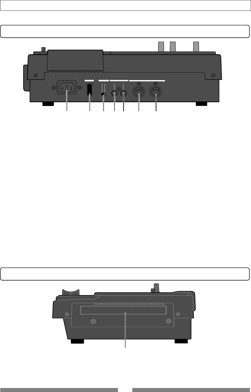
Rear panel
Side panel
56. Slot for the optional CD-RW drive
• You can install the Model CD-1A optional CD-RW drive
in this slot.
• See page 134 for details about how to install the optional
CD-RW drive.
If you want to know details about the option, contact
your dealer or a Fostex sales office.
49. [AC IN] connector
• Connects the supplied AC power cord. Make sure that
the voltage of your AC outlet matches the specified
voltage.
50. [POWER] switch
• Turns on or off the power of the unit.
51. [PHANTOM] ON/OFF switch
• When the switch is set to ON, the phantom power is
supplied to the condenser microphone(s) connected to
the [INPUT A/BAL] and/or the [INPUT B/BAL] connector(s).
52. [S/P DIF / DATA OUTPUT] connector
• Outputs the S/P DIF digital signal. Used to connect to
the coaxial (S/P DIF) digital input of an external digital
device.
If the external device only provides the optical digital
input, use the Fostex COP-1 coaxial/optical converter.
• Connector: RCA pin jack
53. [S/P DIF / DATA INPUT] connector
• Accepts the S/P DIF digital signal. Used to connect to the
coaxial (S/P DIF) digital output of an external digital
device. If the external device only provides the optical
digital output, use the Fostex COP-1 coaxial/optical
converter.
• Connector: RCA pin jack
54. [MIDI OUTPUT] connector
• Connects to the MIDI IN connector of an external MIDI
device.
• Mainly transmits MIDI information for synchronization
such as MTC (MIDI Time Code) and MIDI clock with song
position pointer.
• Connector: DIN 5-pin type
55. [MIDI INPUT] connector
• Connects to the MIDI OUT connector of an external MIDI
device.
• Mainly receives MIDI control information such as MMC
(MIDI Machine Control).
• Connector: DIN 5-pin type
See an appropriate section for the detailed information of
each operation or function.


