


L4421A 40-Channel Armature Multiplexer 4
L4400 User’s Guide 105
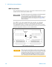
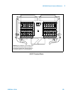
the current ( I ) and LO (L) terminals of ABus1. Through ABus1 and ABus2
you can connect any of the channels to a DMM for voltage or resistance
measurements. Refer to the simplified schematic on page 106.
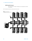
You can control each of the channel switches individually, and thus configure
the instrument in these modes:
• two independent 20- channel 2- wire MUXes. This configuration requires
neither using external wiring nor connecting through the internal Analog
Buses.
• one 20- channel 4- wire MUX. This configuration requires neither using
external wiring nor connecting through the internal Analog Buses.
For 4-wire resistance measurements, the instrument automatically pairs
channel n on Bank 1 with channel n+20 (Bank 2) to provide the source
and sense connections. Four-wire controls require execution of the
ROUTe:CHANnel:FWIRe command or scanning a channel previously
configured as 4- wire.
• one 40- channel 2- wire MUX. You must use external wiring or connect
through the internal analog bus relays for this configuration. For example,
closing analog bus channels 913 and 923 connects Bank 1 and Bank 2
through ABus3. Or, externally you can connect COM1 to COM2 to create
this configuration.
Low thermal offset voltage makes the L4421A ideal for low- level signal
switching. The 34921T optional terminal block provides a built- in
thermocouple reference junction that helps minimize errors due to thermal
offset when you measure thermocouples.
The L4421A has the capability to scan as many as 100 channels/second using
modern DMMs. With the automatic “break- before- make” connection
operation, you are assured that no two signals are connected to each other
during a scan. When using the module in a non- scanning mode, you can close
as many channels as you wish.
This module is safety interlock protected, which means whenever the D- sub
connector end of the instrument is exposed, the analog bus relays
automatically open and disconnect from the analog bus. For more
information, refer to page 100 and page 107.
When power is off, all channel relays maintain state, and the analog bus
relays open.
NOTE
ABus1 consists of three wires that are used for current and voltage
measurements. You cannot measure current and voltage on ABus1
simultaneously.