


218 L4400 User’s Guide
8 L4450A 64-Bit Digital I/O with Memory and Counter
CONF:COUN:FREQ 1e-3, (@1301)
SENS:COUN:INIT (@1301)
SENS:COUN:FREQ? (@1301)
SENS:COUN:PER? (@1301)
SENS:COUN:PWID? (@1301)
SENS:COUN:DCYC? (@1301)
The CONFigure:COUNter:FREQuency command parameter sets the internal
gate time (to 1e-3 or 1 ms in the above example). You can also set the gate time
using the SENSe:COUNter:GATE:TIME command.
Clock
The general- purpose clock output is derived from the internal time base. The
output clock is divided down from the time base clock such that:
Clock Output (Hz) = (time base frequency)/(divisor)
The time base frequency is 40 MHz. The divisor can be an integer from
2 to 4
6
providing a range of 20 MHz to 10 Hz for the clock output.
The valid values for the clock output rate are: 20 MHz, 13.33 MHz,
10 MHz, 8 MHz, 6.667 MHz, ... 10Hz. The clock output frequency will round to
the nearest achievable frequency.
The commands used to control the clock output are:
SOUR:MOD:CLOC:FREQ {<freq>|MIN|MAX|DEF},<slot>
SOUR:MOD:CLOC {OFF|ON|0|1},<slot>
You can obtain the rounded value of the currently set clock frequency using
the following query.
SOUR:MOD:CLOC:FREQ?
You can also set the logic “high” voltage level for external clock output.
For example, the following command sets the output clock level to 4.5 V.
SOUR:MOD:CLOC:LEV 4.5, 1
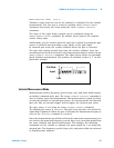
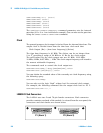
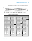
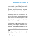
L4450A D-Sub Connectors
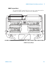
The L4450A uses two D- sub 78- pin female connectors. Each connector
provides contains one bank of the module. As viewed from the rear panel, the
connectors and their banks are shown below.
P1 (Bank 1)
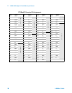
P2 (Bank 2)