


140 L4400 User’s Guide
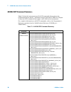
7 Microwave Switch/Attenuator Driver
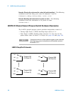
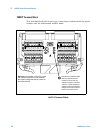
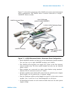
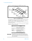
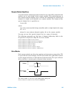
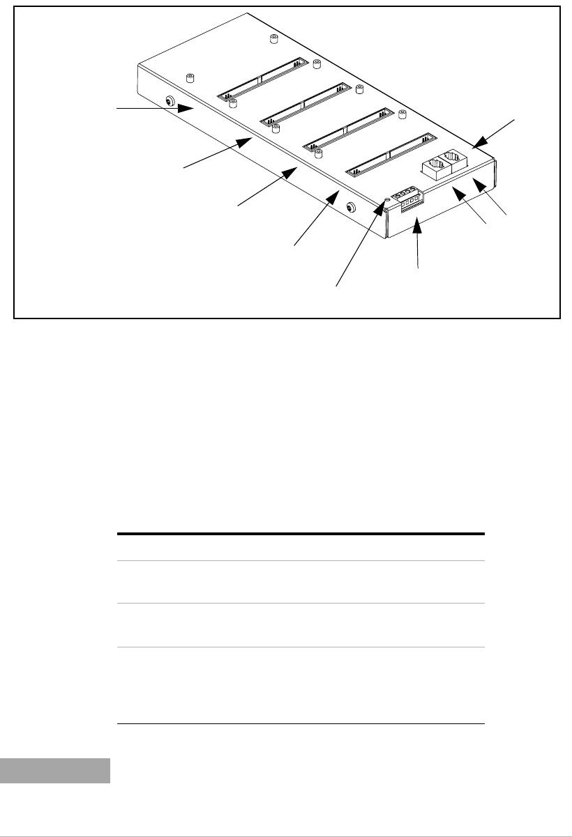
Figure7-2 is a labeled drawing of the 34945EXT remote module.
Figure 7-2. The 34945EXT Module.
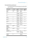
Each 34945EXT has an I/O Access LED used to indicate transactions between
the L4445A and the 34945EXT module. When power is first applied to a
34945EXT module, this LED is continuously illuminated.
After the module has booted, the LED illuminates only intermittently during
programming operations.
Should the L4445A encounter problems communicating with the 34945EXT
the LED is continuously illuminated.
External Power
Supply Connections
Expansion Bus
Port 1
Port 2
I/O Access LED
Bank 1
Ch 1 - 8
Ch 11 - 18
Bank 2
Ch 21 - 28
Ch 31 - 38
Bank 3
Ch 41 - 48
Ch 51 - 58
Bank 4
Ch 61 - 68
Ch 71 - 78
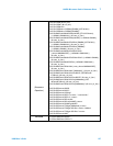
LED Meaning
Not Illuminated Power is not applied to the module or the
module is not processing commands.
Continuously
Illuminated
The 34945EXT is not booted, either due to
an internal error or an L4445A error.
Blinking
Intermittently
Normal operation during command
transactions. Send the
SYSTem:CTYPe:RMODule? query to
initiate a transfer and blink the LED.
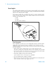
NOTE
Always tighten the screws securing the L4445A sub-assembly to the
instrument carrier assembly, and the screws on both ends of the D-Sub
cable. Incorrect grounding can cause malfunctions of the modules due to
electro-static discharge.