


202 L4400 User’s Guide
8 L4450A 64-Bit Digital I/O with Memory and Counter
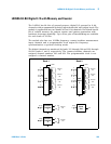
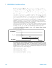
You can set a channel to output in either active drive or open collector
configurations. When set to ACTive, the module drives the digital lines for both
high and low. The voltage level that represents a logic ‘1’ can be set using the
SOURce:DIGital:LEVel command. Output voltages can range from 1.66 V
(default) to 5 V.
When the channel is set to
OCOLlector, lines are driven low, but set to high
impedance (Hi- Z) when asserted. In the open collector mode, multiple lines
can be connected together by providing external pull- ups.
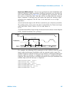
Once a channel has been configured, write digital data to the channel using the
SOURce:DIGital:DATA command.
SOUR:DIG:DATA:LWOR 26503,(@1201)
You may also use a hexadecimal format to represent values in the commands.
For example, to send the decimal value of 26503 in hex use the command form:
SOUR:DIG:DATA:LWOR #h6787,(@1201)
Note that the data should match the channel width configured using
CONFigure:DIGital:DATA:WIDTh command. The data written is masked
by the configured width so that any extra bytes will be discarded.
For example: sending the value 65531 to a byte wide channel will result
in the channel discarding the upper byte and outputting 251.
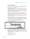
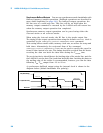
Channel Width and Polarity, Threshold, Level, and Drive
When the width of a channel is set to WORD or LWORd, the channel direction
(input or output) of the channels spanned by the width is controlled by the
channel in operation. That is, all grouped channels are automatically set to the
same input or output operation.
Channel settings of polarity, threshold, level, and drive mode are unchanged
when channels are combined. For example, consider the following command
sequence.
CONF:DIG:POL NORM,(@1101)
CONF:DIG:POL INV,(@1102)
CONF:DIG:WIDT WORD,(@1101)
NOTE
When using external pull-ups in the open collector mode, the outputs will
not exceed 5 V.
NOTE
Writing to a channel automatically configures the channel as an output.