


208 L4400 User’s Guide
8 L4450A 64-Bit Digital I/O with Memory and Counter
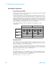
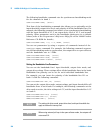
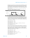
Synchronous Buffered Outputs You can use synchronous mode handshake with
buffered (memory) output operations. (Buffered operations are described in
more detail beginning on page 210.) For buffered output operations, the
H0 line acts as a start/stop line. This line will be set high when the
memory output command is executed by the L4450A and will return low
when the memory output operation has completed.
Synchronous memory output operations can be paced using either the
internal strobe or an external strobe.
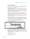
When using the internal strobe, the H1 line is the strobe output line.
The timing of the output operation when using the default
INTernal clock is
controlled by the CONFigure:DIGital:HANDshake:RATE command.
This setting affects strobe width, memory clock rate, as well as the setup and
hold times. Alternatively, the reciprocal form of the command
CONFigure:DIGital:HANDshake:CTIMe can be used to specify the speed in
terms of time instead of a rate. The timing should be set such that the device
receiving the data can latch the data lines during the T
CYCLE
time.
The receiving device should detect the leading edge of the strobe line, wait for
the L4450A to set the data (T
PD
) and then latch the data. Latching the data on
the trailing edge of the strobe is recommended, however, you can the data
following T
PD
. T
PD
ranges from - 23 to 23 ns.
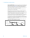
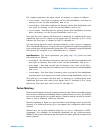
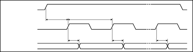
A synchronous buffered output using the internal clock is shown in the
diagram below (default handshake line polarity).
H0 (Start/Stop)
H1 (Strobe Out)
Data Out
Valid
T
CYCLE
(Last Cycle)
Invalid
T
PD
T
PD
T
PD
T
CYCLE
/ 2