


236 L4400 User’s Guide
10 L4452A Multifunction Module with DIO, D/A, and Totalizer
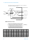
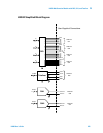
L4452A Multifunction Module
The L4452A Multifunction Module with DIO, D/A, and Totalizer combines
four 8- bit ports of digital input/output, a 100 kHz totalizer, and two ±12
volt earth- referenced analog outputs. You can include digital inputs and
totalizer input in a scan list. You can make connections via standard
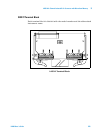
50- pin D- sub cables or the optional 34952T terminal block.
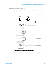
Digital Input/Output
The Digital Input/Output (DIO) consists of four 8- bit ports with
TTL- compatible inputs and output. The open- drain outputs can sink up
to 400 mA. You can configure the DIO ports for 8, 16, or 32- bit
operations. The DIO channels are connected by internal 5 V pull- up
resistors when configured as inputs.
Totalizer Input
The 32- bit totalizer can count pulses up to 100 kHz. You can configure
the totalizer to count on the rising edge or falling edge of the input
signal. A TTL high signal applied to the Gate terminal enables counting
and a low signal disables counting. A TTL low signal applied to the
Not-Gate terminal enables counting and a high signal disables counting.
The totalizer counts only when both terminals are enabled.
Analog Output (DAC)
The two analog outputs are capable of outputting voltages between ±12
volts with 16 bits of resolution. Each DAC channel is capable of
driving/sinking 10 mA maximum current. You can use the two analog
outputs to source bias voltages to your DUT, to control your analog
programmable power supplies, or as set points for your control systems.
NOTE
When the gate is not connected, the gate terminal is pulled to the
enabled state, effectively creating a “gate always” condition.