


184 L4400 User’s Guide
7 Microwave Switch/Attenuator Driver
Simplified Connection Diagrams
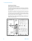
Single Drive With Separate Position Indicators
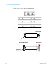
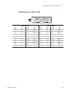
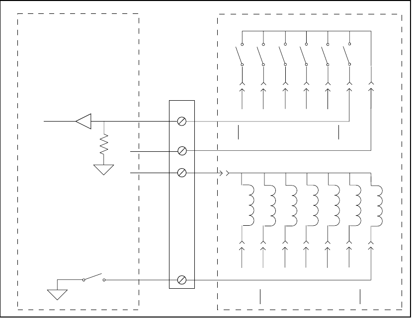
The simplified schematic below illustrates the connection for a single drive
switch with separate position indicators. The position indicators for this type
of switch are independent relay contacts that are mechanically linked to the
RF switch position.
Even though this is a single drive switch, each switch state has its own coil.
The switch uses internal logic to open all paths except the one being closed.
The RF paths are not shown in the simplified diagram. The coils are driven in
open collector mode. The position indicator is set so that a high level indicates
an active switch. The logic level of the position indicator can be inverted using
the
ROUTe:CHANnel:VERify:POLarity command.
The schematic shown is similar to the Agilent 87104A/B/C, 87106A/B/C, and
87406B switches. Many other switches use this technique (both with and
without the position indicator).
34945EXT
Y1155A
Distribution
Board
Switch
6543 2 1
1345
6
2Open
All
IND 1
+VI
+VR
DRV 1
Logic Gate
Sense
Pull Down
Resistor
Open Collector
Output Driver
To DRV 2 through 6To DRV 7
To IND 2 through 6