


172 L4400 User’s Guide
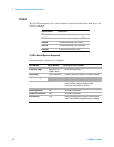
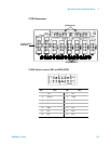
7 Microwave Switch/Attenuator Driver
8494/5/6
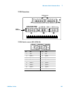
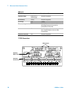
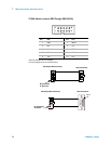
Y1153A Attenuator Control
All channel are operated in PAIRed mode.
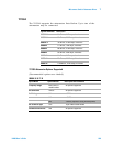
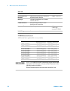
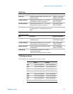
Item Description Example Part Numbers
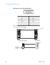
Cable Supplied with
Attenuator
Cable with Viking connector on attenuator
end, bare wires on other end
Agilent 8120-2178
Cable Type 12 conductor round cable, 22 or 24 AWG
stranded, 0.25" dia.
Y1153A Connection Screw terminals provided on Y1153A
distribution cable connection
Attenuator Connector 12 pin Viking Industries, Inc. circular connector Viking connector body
TNP12-102P
contacts TS-100-AU
Cable Wiring See attenuator manual
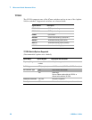
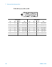
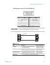
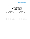
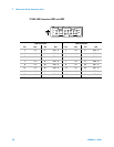
Attenuation Section In Attenuation Section Out
ATTEN 1 SECTION 1 ROUT:OPEN (@xx01) ROUT:CLOS (@xx01)
ATTEN 1 SECTION 2 ROUT:OPEN (@xx02) ROUT:CLOS (@xx02)
ATTEN 1 SECTION 3 ROUT:OPEN (@xx03) ROUT:CLOS (@xx03)
ATTEN 1 SECTION 4 ROUT:OPEN (@xx04) ROUT:CLOS (@xx04)
ATTEN 2 SECTION 1 ROUT:OPEN (@xx05) ROUT:CLOS (@xx05)
ATTEN 2 SECTION 2 ROUT:OPEN (@xx06) ROUT:CLOS (@xx06)
ATTEN 2 SECTION 3 ROUT:OPEN (@xx07) ROUT:CLOS (@xx07)
ATTEN 2 SECTION 4 ROUT:OPEN (@xx08) ROUT:CLOS (@xx08)
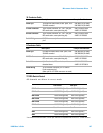
NOTE
ROUTe:OPEN adds that section's attenuation amount to the overall
attenuation. Total attenuation is the sum of the dB amounts for the
individual sections switched in.
When all channels open at reset maximum attenuation is set.