


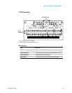
Microwave Switch/Attenuator Driver 7
L4400 User’s Guide 185
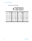
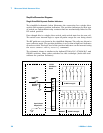
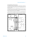
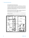
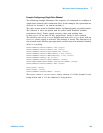
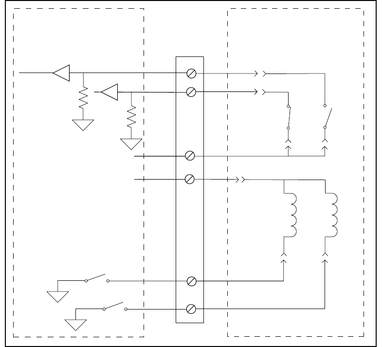
Paired Drive With Separate Position Indicators
The simplified schematic below illustrates the connection for a dual drive
switch with separate position indicators. The position indicators for this type
of switch are independent relay contacts that are mechanically linked to the
RF switch position.
The RF paths are not shown in the simplified diagram. The coils are driven in
open collector mode. The position indicator is set so that a high level indicates
an active switch. The logic level of the position indicator can be inverted using
the
ROUTe:CHANnel:VERify:POLarity command.
As shown, Channel 01 was pulsed to close Coil A. The corresponding position
indicator also closed. Closing position indicator A opens position indicator B.
The schematic shown is similar to the Agilent N181x series of switches.
34945EXT
Y1155A
Distribution
Board
Switch
IND 11
IND 1
+VI
+VR
DRV 1
DRV 11
Open Collector
Output Drivers
Logic Gate
Sense
Pull Down
Resistor
A
B
Coil A
Coil B