


10 L4400 User’s Guide
1 Introduction to the L4400 Series LXI Instruments
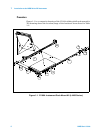
4. Install the second L4400 instrument (if present) in the shelf area adjacent
to the first instrument. If only one instrument is installed, install a filler
panel on the front edge of the unused area. Insert two M4x8 flat head screws
(item 1) upward through the bottom of the shelf and into the panel.
5. Connect the instrument power cord, LAN cable, and GPIB cable if present.
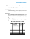
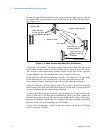
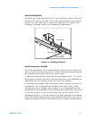
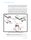
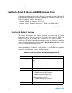
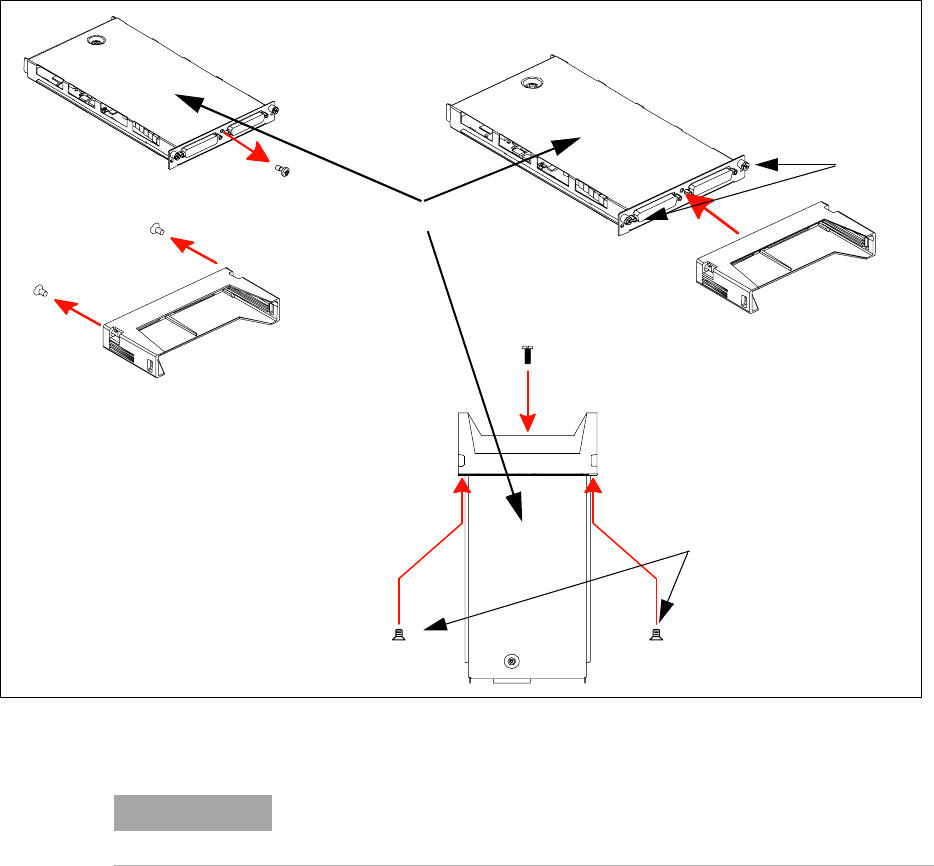
6. For instruments that have accompanying terminal blocks, partially remove
the instrument sub-assembly from the instrument (carrier) by loosening the
spring- loaded mounting screws (Figure 1- 5). Remove the support sleeve from
the terminal block. Locate and remove the flat head screws from the sleeve
and remove the pan head screw from between the instrument’s D- sub
connectors (Figure 1-5). Connect the sleeve to the instrument using the flat
head and pan head screws as shown. Reconnect the sub- assembly.
Figure 1-5. Connecting the Terminal Block Support Sleeve.
terminal block
flat head screws
support sleeve
pan head screw
pan head screw
flat head screws
spring-loaded
mounting screws
instrument sub-assembly
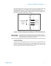
NOTE
Refer to Chapters 4-10 for information on Terminal Block wiring and
connecting the terminal block to the instrument.