


206 L4400 User’s Guide
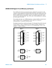
8 L4450A 64-Bit Digital I/O with Memory and Counter
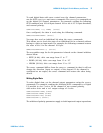
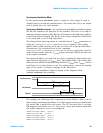
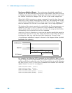
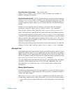
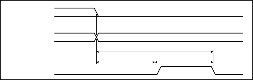
Synchronous Unbuffered Outputs For synchronous handshake unbuffered
outputs, the H0 line indicates the direction of the transfer. This line is set low
to indicate an output operation. The H0 line will remain in the low state until
the L4450A direction is changed. The H1 line is the strobe output line.
When the L4450A executes an output command, it sets the data lines and
waits for T
CYCLE
/2 before asserting the strobe line. The leading edge of the
strobe indicates the data is valid. The strobe line is asserted for T
CYCLE
/2 and
then de- asserted. The H2 line is not used and is set to high impedance.
The timing of the output operation is controlled by the T
CYCLE
parameter set
using the CONFigure:DIGital:HANDshake:RATE command. This setting
affects strobe width, memory clock rate, as well as the setup and hold times.
Alternatively, the reciprocal form of the command
CONFigure:DIGital:HANDshake:CTIMe can be used to specify the speed in
terms of time instead of a rate. The timing should be set such that the device
receiving the data can read the data lines during the T
CYCLE
/2 time.
A synchronous unbuffered output is shown in the diagram below (default
handshake line polarity).
For example, the following SCPI commands set the L4450A to have a 16- bit
output using synchronous handshake. Two data outputs are then performed
and the strobe line is pulsed for each. The I/O direction line is set low following
the first
SOURce:DIGital:DATA:WORD command and remains low until the
digital channel is reset of reconfigured.
CONF:DIG:WIDT WORD, (@1101)
CONF:DIG:DIR OUTP, (@1101)
CONF:DIG:HAND SYNC, (@1101)
SOUR:DIG:DATA:WORD #hFFFF, (@1101)
SOUR:DIG:DATA:WORD #h4DB5, (@1101)
H0 (Direction)
H1 (Strobe)
Data Out
Invalid Valid
T
CYCLE
T
CYCLE
/ 2 T
CYCLE
/ 2