


8 L4400 User’s Guide
1 Introduction to the L4400 Series LXI Instruments
If center- facing columns with holes are present on the frame, insert a clip- on
nut on the hole perpendicular to the center hole on the front facing column.
See Figure 1-3.
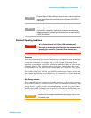
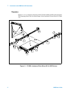
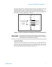
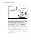
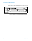
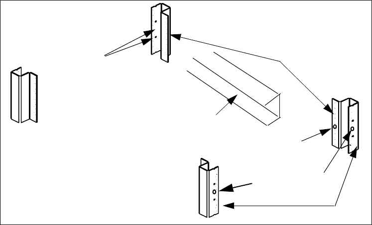
Figure 1-3. Rack Column and Shelf Rail Orientation.
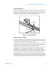
2. With the rail “channel” facing the center of the rack, connect the rail to the
front facing column using a 10- 32 flathead screw (item 4) and the center
clip-on nut on the front- facing column. Repeat for the rail on the opposite
column. Ensure the rail channel faces the center of the rack.
If the rack has center-facing columns (Figure 1- 3), insert a 10- 32 pan head
screw through the rail opening and clip nut (perpendicular to the
front- facing column). Repeat for the rail on the opposite column.
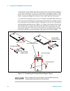
3. On the rack’s rear- facing columns, insert clip- on nuts on the first and third
holes between the EIA unit indicators that are at the same vertical position
as the indicators on the front-facing columns.
4. Attach the rear brackets to the rail ends using two 10- 32 pan head screws
(item 3) and two 10- 32 nuts with lockwashers (item 6) per rail. Adjust the
bracket along the rail until the bracket end aligns with (covers) the rack’s
rear-facing columns. Tighten the 10-32 pan head screws to firmly connect the
bracket to the rail and maintain the rail length.
Connect the rail brackets to the rear- facing columns using two 10- 32 pan
head screws per column.
(center of rack)
front-facing colums
center-facing colums
back of rack
insert clip nuts
between rack unit
indicators
insert clip nut
if column present
insert clip nuts
on first and third
holes between indicators
rail “channel