


Microwave Switch/Attenuator Driver 7
L4400 User’s Guide 139
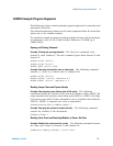
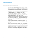
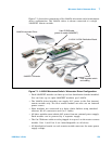
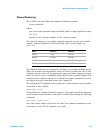
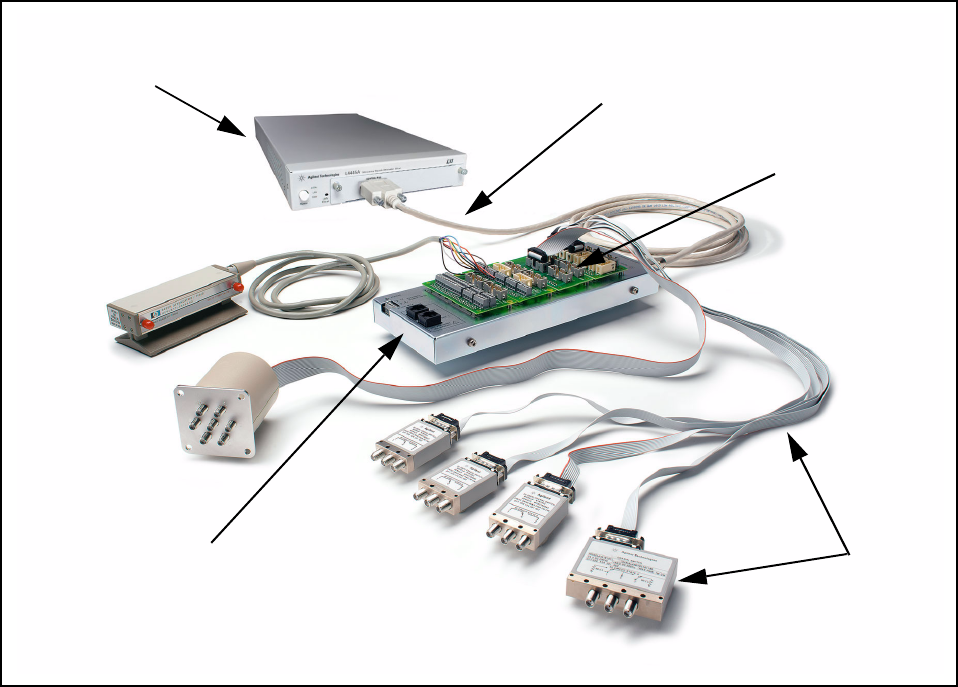
Figure 7-1 shows the components of the L4445A microwave switch/attenuator
driver configuration. The L4445A driver is shown connected to a single
34945EXT remote module.
Figure 7-1. L4445A Microwave Switch / Attenuator Driver Configuration.
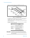
• Each 34945EXT module can have up to four distribution boards installed.
You can have up to eight 34945EXT modules per L4445A.
• The L4445A driver interface can supply 24 V power to the first (master)
remote module only. The first remote module can also use an external
power source..
• Slave modules are connected in a daisy chain fashion using standard
ethernet RJ- 45 connectors and Cat 5 cables.
• All slave modules must obtain 24V power from an external power supply.
Each module can be powered by a separate supply.
• The Cat 5 Ethernet cable must be plugged- in to port 1 on the master remote
module. Port 1 and Port 2 are interchangeable on all slaves.
• All distribution boards on each remote module must use the same power
supply voltage.
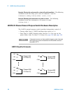
L4445A Instrument Driver
Y1150A-Y1155A Distribution Board
9-pin D-SUB cable
(power to master 34945EXT)
34945EXT Extender
User-supplied switch
and cabling