228 L4400 User’s Guide
9 L4451A 4-Channel Isolated D/A Converter with Waveform Memory
L4451A Example Program Segments
The programming examples below provide you with SCPI command
examples to use for actions specific to the DAC module.
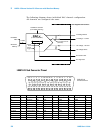
The slot and channel addressing scheme used in these examples follow
the form 1ccc where ccc is the three-digit channel number. Valid channels for
this module are 001- 004. For information on specific configurations, refer to
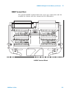
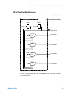
the simplified schematic on page 231.
For detailed example programs involving multiple drivers and development
environments, refer to the L4400 Product Reference CD- ROM (p/n
34989- 13601).
Level Mode
Example: Outputting a DC voltage level This command sets the output voltage
level for the specified DAC channels. After setting the desired level, send the
OUTPut:STATe command to close the corresponding output relay and
enable outputs from the specified channels. The following command outputs
+2.5 V DC on DAC channels 1 and 2.
SOURce:VOLTage 2.5,(@1001,1002)
OUTPut:STATe ON,(@1001,1002)
Example: Outputting a current level This command sets the output current
level on the specified channels on the DAC module. After setting the desired
level, send the OUTPut:STATe command to close the corresponding output
relay and enable outputs from the specified channels. The following
command outputs +5 mA on DAC channels 1 and 2 and closes the output
relay.
SOURce:CURRent 5E-3,(@1001,1002)
OUTPut:STATe ON,(@1001,1002)
(Sequence
Operation)
ROUTe:SEQuence:CATalog?
ROUTe:SEQuence:DEFine <name>, "<commands>"
ROUTe:SEQuence:DEFine? <name>
ROUTe:SEQuence:DELete:ALL
ROUTe:SEQuence:DELete[:NAME] <name>
ROUTe:SEQuence:DONE?
ROUTe:SEQuence:TRIGger[:IMMediate] <name>
ROUTe:SEQuence:TRIGger:SOURce <name>, MANual
ROUTe:SEQuence:TRIGger:SOURce? <name>
ROUTe:SEQuence:WAIT


