


Microwave Switch/Attenuator Driver 7
L4400 User’s Guide 151
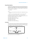
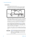
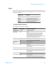
LED Drive
The distribution boards contain a ribbon cable header you can use to connect
LEDs to provide a visual indication of switch state. These lines reflect the state
of their corresponding channel’s position indicator. Some systems use LEDs as
a graphical indicator of switch positions.
Use the
ROUTe:RMODule:BANK:LED:DRIVe:LEVel command to set the drive
current for the LEDs. You do not need to provide an external current
limiting resistor. This command uses special channel addressing as
described in “Remote Module Identifiers” on page 145.
Once the drive current is set, enable the LED drives using the
ROUTe:RMODule:BANK:LED:DRIVe:ENABle command. This command uses
special channel addressing as described in “Remote Module Identifiers” on
page 145.
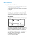
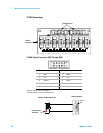
Simplified connections for the position indicators are shown in the diagrams
beginning on page 184.
NOTE
The LEDs obtain their power from the remote module power supply. If the
ROUTe:RMODule:DRIVe:SOURce OFF command has been sent, the
LEDs will not operate.