


102 Altera Corporation
32-Bit Instruction Set
TRAP
Unconditional Trap
Operation: ISTATUS ← STATUS
IE ← 0
CWP ← CWP − 1
IPRI ← IMM6
%o7 ← ((PC + 2) >> 1)
PC ← Mem32[VECBASE + (IMM6 ×4)] << 1
Assembler Syntax: TRAP IMM6
Example: TRAP 0 ; reset the board
Description: CWP is decremented by one, opening a new register-window for the trap-handler.
Interrupts are disabled (IE ← 0). The pre-TRAP STATUS register is copied into the
ISTATUS register.
Transfer execution to trap handler number IMM6. The address of the trap-handler
is read from the vector table which starts at the memory address VECBASE
(VECBASE is configurable). A 32-bit value is fetched from the word-aligned
address (VECBASE + IMM6 × 4). The fetched value is multiplied by two and
transferred into PC. The address of the instruction immediately following the
TRAP instruction is placed in %o7. The value in %o7 is suitable for use as a
return-address for TRET without modification. The return-address convention for
TRAP is different than BSR/CALL, because TRAP does not have a delay-slot.
A TRAP instruction will transfer execution to the indicated trap-handler even if the
IE bit in the STATUS register is 0.
Condition Codes: Flags: Unaffected
Delay Slot Behavior: TRAP does not have a delay slot. The instruction immediately following TRAP is
not executed before the target trap-handler. The return-address used by TRET
points to the instruction immediately following TRAP.
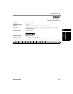
Instruction Format: i6v
Instruction Fields: IMM6 = 6-bit immediate value
NVZC
−−−−
1514131211109876543210
011110 0100 IMM6