


2-5
MGP 464 • Installation
PRELIMINARY
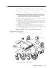
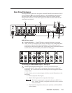
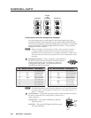
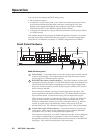
Rear Panel Features
The diagram below shows the rear panel of the MGP 464 DI, which has four DVI-I
input connectors (
j
in the illustration below). The standard MGP 464 does not
have these DVI input connectors (although it does have DVI Output and DVI
Background connectors). In all other respects the MGP 464 and the MGP 464 DI
rear panels are identical.
9
.5A MAX
100
-
240
50/60 Hz
1
INPUT 1-DVI-D
R
R-Y
G/Y
VID
H/HV
V
H/HV
B/C
B-Y
2
R
R-Y
G/Y
VID
H/HV
V
H/HV
B/C
B-Y
3
R
R-Y
G/Y
VID
H/HV
V
H/HV
B/C
B-Y
45
R
R-Y
G/Y
VID
H/HV
V
H/HV
B/C
B-Y
R/
R-Y
VID
Y
6
VID
B-Y
C
7
VID
R-Y
8
VID
Y
9
VID
B-Y
C
10
VID
R-Y
11
VID
Y
12
VID
B-Y
C
13
VID
R-Y
14
VID
Y
15
VID
B-Y
C
16
VID
R-Y
17
VID
Y
18
VID
B-Y
C
19
VID
R-Y
G/Y
B/
B-Y
H/
HV
V
INPUT 2-DVI-D INPUT 3-DVI-D INPUT 4-DVI-D
DVI-D BACKGROUND
INPUT
DVI-D OUTPUT
RGB/Y, R-Y, B-Y OUTPUT
RS-232/422
LAN
R
VIRTUAL VIDEO INPUTSRGB VIDEO INPUTS
7
8
10
11
4
6
2
1
5
3
MGP 464 rear panel
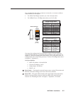
1
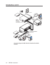
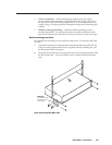
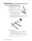
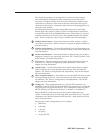
Inputs 1 through 4 — Plug RGB, high or standard denition component
video, S-video, or composite video sources into these fully congurable BNC
connectors, as shown in the following diagram. These connectors can be
congured for the desired signal types via the front panel, the Windows-based
control software, SIS commands, or the MGP 464 Web pages.
RGBHV
Video
RGsB or
Component
Video
S-Video Composite
Video
RGBS or
RGBcvS
Video
H/HV
V
R/R-Y
G/Y
VID
B/C
B-Y
H/HV
B/C
B-Y
H/HV
V
R/R-Y
G/Y
VID
B/C
B-Y
V
R/R-Y
G/Y
VID
B/C
B-Y
H/HV
V
R/R-Y
G/Y
VID
B/C
B-Y
H/HV
V
R/R-Y
G/Y
VID
11111
Connecting to RGB/HD/VIDEO inputs 1 through 4
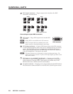
2
Virtual inputs (inputs 5 through 19) — Connect standard definition
component video, S-video, and/or composite video sources to these BNC
connectors. The 15 connectors for the virtual inputs are arranged in columns
of three BNCs.
In each column, you can connect inputs as follows (see the illustration on the
next page):
Three composite video inputs
•
One S-video input and one composite video input•
The S-video must always be connected to the top two BNCs (Y on
top, C second). If desired, a composite video source can be connected
to the bottom BNC.
One interlaced component video source (connects to all three BNCs
•
in the column).