


Operation, cont’d
MGP 464 • Operation
3-10
PRELIMINARY
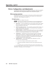
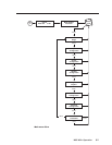
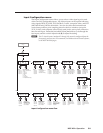
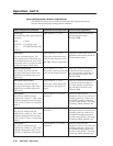
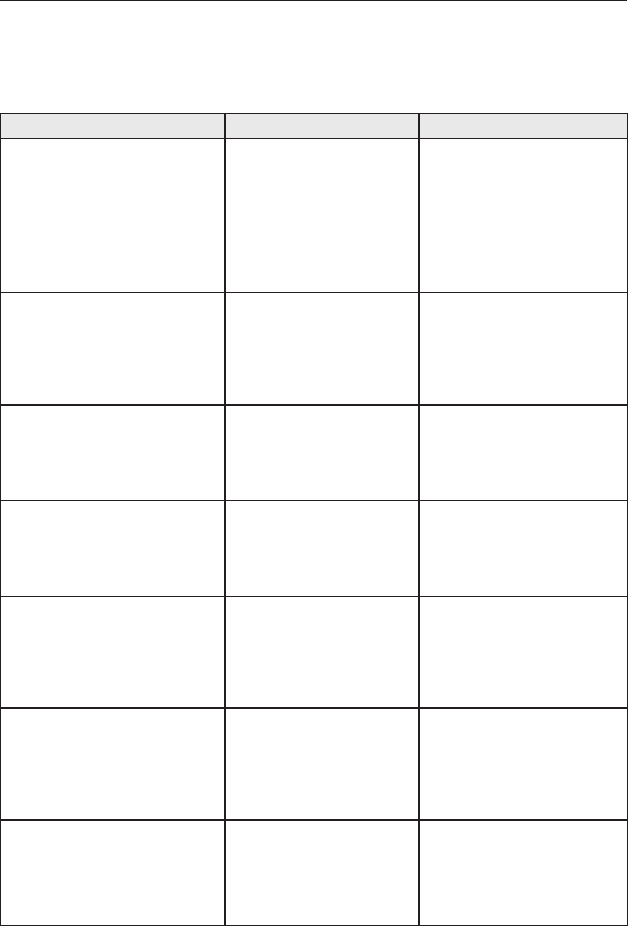
Input conguration submenu adjustments
The table below shows how to make the selections and adjustments that are
accessed through the Input Configuration submenus.
Input Conguration submenu Horizontal Knob Adjustment Vertical Knob Adjustment
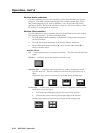
Video type
The following video signal types are
accepted:
RGB S-video
YUV-HD Composite video
YUVi DVI (MGP 464 DI only)
RGBcvS
Select input #1, 2, 3, or 4. Select the desired video format
for the displayed input.
Default: RGB
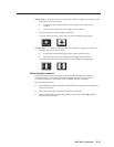
Film mode
For low resolution inputs. The
video signal type for the input you
are conguring must be set to YUVi,
composite video, or S-video in order
to place the input in film mode.
Select input #1, 2, 3, or 4.
Shows the current film mode
status for the displayed input:
On, Off, or na (not applicable).
Select On or Off to turn 3:2 or 2:2
pulldown (film mode) on and off
for the selected input.
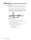
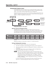
Vertical start position
The distance in pixels from the
top edge of the input’s total video
display area to the top edge of its
active area
Select input #1, 2, 3, or 4.
Shows the current vertical start
point for the displayed input.
Increase or decrease the distance
in pixels from the top edge of
the video display’s total area to
the top edge of its active area.
Default is 128.
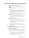
Horizontal start position
The distance in pixels from the
left edge of the input’s total video
display area to the left edge of its
active area
Select input #1, 2, 3, or 4.
Shows the current horizontal
start point for the displayed
input.
Increase or decrease the distance
in pixels from the left edge of
the video display’s total area to
the left edge of its active area.
Default is 128.
Pixel phase 1
The point at which pixels are
sampled for window 1. (The values
cannot be changed when the input
is DVI, YUVi, S-video, or composite
video.)
Select input #1, 2, 3, or 4 for
window 1.
Increase or decrease the
displayed value to move the pixel
sampling point for window 1 to
an optimal sampling point that
ensures output clarity. The range
of settings is 0-31; default is 16.
Pixel phase 2
The point at which pixels are
sampled for window 2. (The values
cannot be changed when the input
is DVI, YUVi, S-video, or composite
video.)
Select input #1, 2, 3, or 4 for
window 2.
Increase or decrease the
displayed value to move the pixel
sampling point for window 2 to
an optimal sampling point that
ensures output clarity. The range
of settings is 0-31; default is 16.
Pixel phase 3
The point at which pixels are
sampled for window 3. (The values
cannot be changed for DVI, YUVi,
S-video, or composite video inputs.)
Select input #1, 2, 3, or 4 for
window 3.
Increase or decrease the
displayed value to move the pixel
sampling point for window 3 to
an optimal sampling point that
ensures output clarity. The range
of settings is 0-31; default is 16.