


MGP 464 • Quick Start
QS-1
PRELIMINARY
Quick Start — MGP 464
Installation
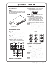
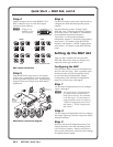
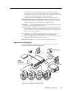
Step 1
Install the four rubber feet on the bottom of the
MGP 464, or mount the unit using the supplied
rack mounting brackets.
Rack mounting the MGP 464
Step 2
Turn off power to the input and output devices,
and remove the power cords from them.
Step 3
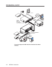
Attach the input devices to the MGP 464. The
following input signal types are accepted:
Inputs 1, 2, 3, and 4 — RGB, component
video, S-video, or composite video (fully
configurable)
Connecting to inputs 1 through 4
DVI inputs 1, 2, 3, and 4 — DVI. These inputs
can be used instead of analog inputs 1
through 4. (MGP 464 DI only)
N
Analog is not available on this DVI-I
connector.
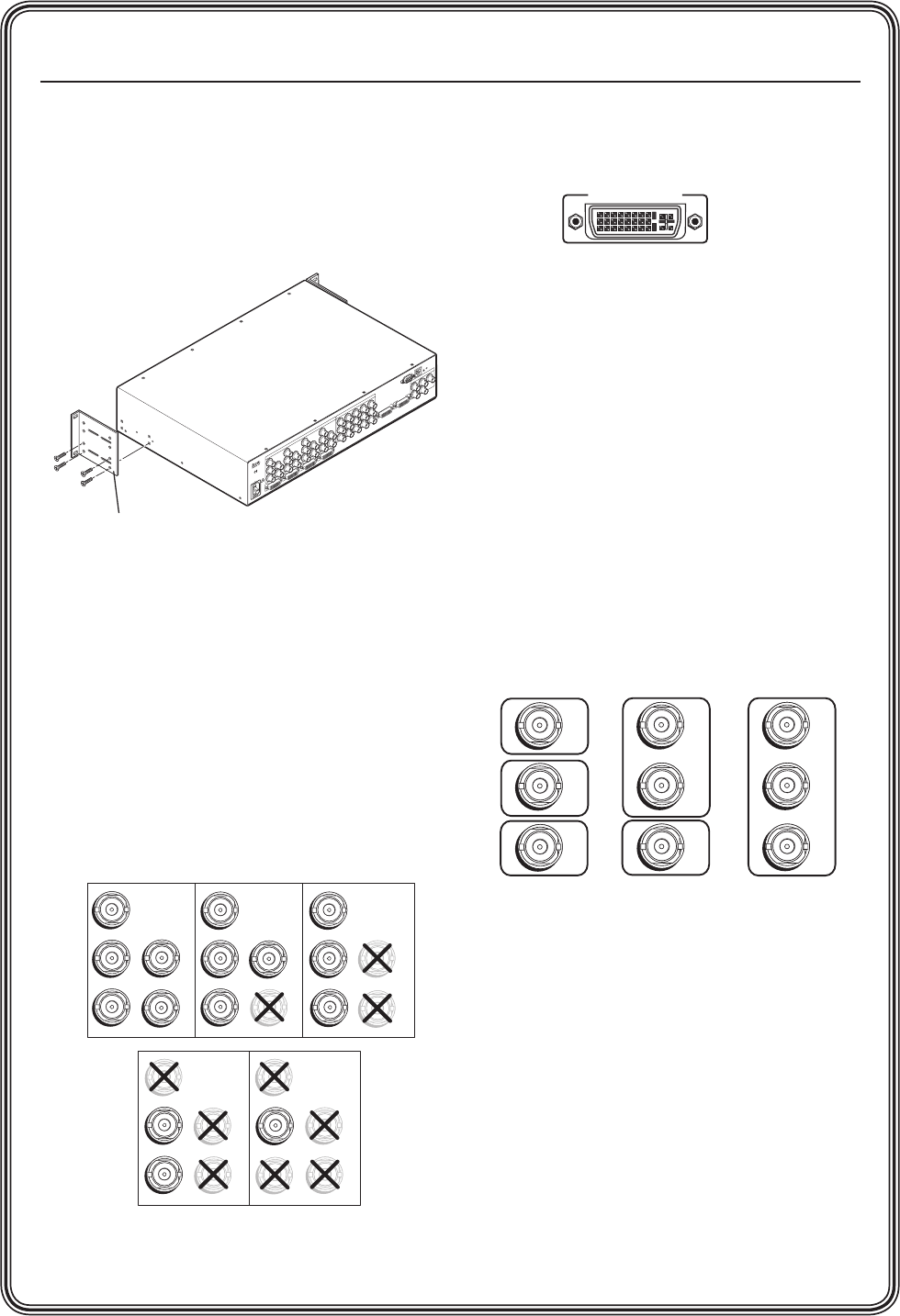
Virtual inputs 5 – 19 — Component video,
S-video, or composite video (configurable
via Windows
®
-based control software, SIS
™
commands, or Web pages only). In each
column, you can connect inputs as follows:
Three composite video inputs
•
One S-video and one composite video input•
N
The S-video must always be connected to
the top two BNCs (Y on top, C second).
If desired, a composite video source can be
connected to the bottom BNC.
One interlaced component video source
•
(connects to all three BNCs in the column).
Virtual input connection examples
DVI Background input — DVI for live
background video only (available on all
models).
The four MGP windows are displayed
in front of this DVI image. When a DVI
background is used, the MGP output
is locked to the input rate of the DVI
background. This input is not scaled.
N
This input connector can be used only to
receive the background image. The input
is not scaled or processed. To process
DVI input signals, you must use the
MGP 464 DI model.
N
Analog is not available on this DVI-I
connector.
RGBHV
Video
RGsB or
Component
Video
S-Video Composite
Video
RGBS or
RGBcvS
Video
H/HV
V
R/R-Y
G/Y
VID
B/C
B-Y
H/HV
B/C
B-Y
H/HV
V
R/R-Y
G/Y
VID
B/C
B-Y
V
R/R-Y
G/Y
VID
B/C
B-Y
H/HV
V
R/R-Y
G/Y
VID
B/C
B-Y
H/HV
V
R/R-Y
G/Y
VID
VID
Y
VID
B-Y
C
VID
R-Y
5
6
7
VID
Y
VID
B-Y
C
VID
R-Y
5
6
7
S-video
and
Composite
Component
VID
Y
VID
B-Y
C
VID
R-Y
5
6
7
Composite
.5A
MAX
10
0
-
240
50/60
Hz
1
IN
P
U
T
1
-D
V
I-D
R
R
-Y
G
/Y
V
ID
H
/H
V
V
H
/H
V
B
/C
B
-Y
2
R
R
-Y
G
/Y
V
ID
H
/H
V
V
H
/H
V
B
/C
B
-Y
3
R
R
-Y
G
/Y
V
ID
H
/H
V
V
H
/H
V
B
/C
B
-Y
4 5
R
R
-Y
G
/Y
V
ID
H
/H
V
V
H
/H
V
B
/C
B
-Y
R
/
R
-Y
V
ID
Y
6
V
ID
R
-Y
C
7
V
ID
B
-Y
8
V
ID
Y
9
V
ID
R
-Y
C
1
0
V
ID
B
-Y
1
1
V
ID
Y
1
2
V
ID
R
-Y
C
1
3
V
ID
B
-Y
1
4
V
ID
Y
1
5
V
ID
R
-Y
C
1
6
V
ID
B
-Y
1
7
V
ID
Y
1
8
V
ID
R
-Y
C
1
9
V
ID
B
-Y
G
/Y
B
/
B
-Y
H
/
H
V
V
IN
P
U
T
2
-D
V
I-D
IN
P
U
T
3
-D
V
I-D
IN
P
U
T
4
-D
V
I-D
D
V
I
B
A
C
K
G
R
O
U
N
D D
V
I
O
U
T
P
U
T
RGB/
Y, R-Y, B-Y OUTPUT
R
S
-
2
3
2
/4
2
2
L
A
N
R
VIRTUAL VIDEO INPU
TS
RGB VIDEO INPU
TS
MBD 249
2-U Rack Mount Bracket
(Use four lower holes.)
INPUT 1-DVI-D