


3-3
MGP 464 • Operation
PRELIMINARY
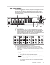
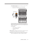
The virtual input buttons are arranged in five columns of three buttons
each, reflecting the arrangement of the virtual input connectors on the
rear panel. Component video sources must be connected to all three input
connectors in a column; S-video sources must be connected to the top two
connectors in the column. Composite video sources can be plugged into any
connector in the column.
Like the buttons for the four fully configurable inputs, the virtual input
buttons light when pressed. When you press an input button connected to
a component video source, all three buttons in its column light. If you press
a button connected to an S-video source, the top two buttons in the column
light. When a composite video source is selected, only one button lights.
4
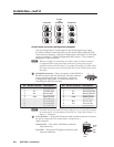
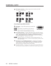
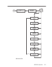
Window Select buttons — Press these buttons to select, activate, or adjust
one of the four windows. While a window is selected, all picture controls are
associated with it.
5
Window Preset buttons — Press the Preset Recall/Save and Enter buttons to
save or recall window presets. See “Window Presets,” later in this chapter, for
more information.
6
Picture control buttons — Press these buttons to adjust image size, position,
brightness, contrast, color, tint, detail, and zoom. See “Picture Controls,” later
in this chapter, for further information.”
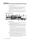
7
LCD screen — This screen displays messages, menu information, and your
selections. See “Menus, Conguration, and Adjustments,” later in this
chapter, for more information.
8
Adjust knobs — Turn these horizontal and vertical Adjust knobs to adjust
picture controls and to scroll through preset memory slots and submenu
options. See “Menus, Conguration, and Adjustments,” later in this chapter,
for more information.
9
Menu navigation buttons — Press Menu to access the MGP 464 menu system
and step through the menus. From each menu, press Next to step through
its submenus. See “Menus, Conguration, and Adjustments,” later in this
chapter, for more information.
10
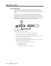
Config port — This configuration port on a 2.5 mm TRS connector is an
alternative to the RS-232/422 port on the MGP rear panel; however, unlike the
rear panel port, it supports only RS-232. (For a description of the rear panel
RS-232/422 port, see “Rear Panel Features” in chapter 2, “Installation”).
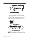
Both of the MGP’s serial ports are used for system conguration and
control. Commands are received through these ports from the PC, using SIS
commands or the Windows-based control software. Both serial ports can be
active at the same time.
The protocol for this configuration port is as follows:
• 9600 baud
• 8 data bits
• 1 stop bit
• No parity
• Always RS-232