


Installation, cont’d
MGP 464 • Installation
2-8
PRELIMINARY
7
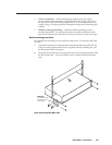
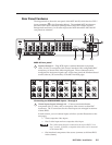
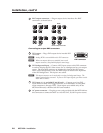
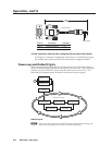
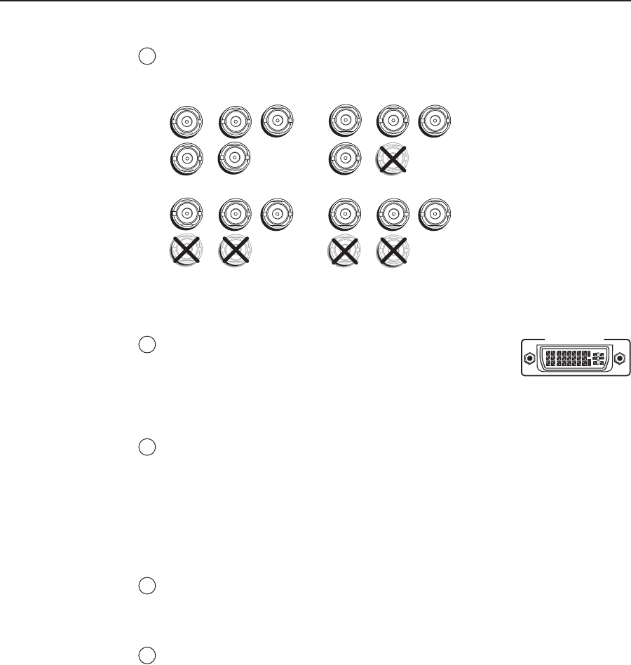
BNC output connectors — Plug an output device into these ve BNC
connectors, as shown below.
R
/R-Y
G
/Y
B
/B-Y
H
/HV
V
R
/R-Y
G
/Y
B
/B-Y
H
/HV
V
R
/R-Y
G
/Y
B
/B-Y
H
/HV
V
R
/R-Y
G
/Y
B
/B-Y
H
/HV
V
RGBHV RGBS
RGsB HD YUV Component Video
Connecting to output BNC connectors
8
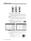
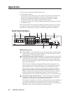
DVI output — Plug a DVI output device into this DVI
connector.
N
Analog RGB is not available on the DVI connector.
N
When two output devices are attached (one to each
output connector), they both display the same image.
9
DVI background input — Connect a DVI input source to this DVI connector
in order to display the DVI video source live as a background on your output
screen. The four MGP windows are displayed in front of this DVI image.
When a DVI background is used, the MGP output is locked to the input rate
of the DVI background. This input is not scaled.
N
This input connector can be used only to receive the background image. The
input is not scaled or processed. To process DVI input signals, you must use the
MGP 464 DI model.
10
DVI inputs 1, 2, 3, and 4 (MGP 464 DI only) — Connect up to four DVI
input sources to these DVI input connectors, as an alternative to using BNC
input connectors 1 through 4 (
a
). These inputs are available only on the
MGP 464 DI model, which has the DVI card installed.
11
AC power connector — Plug the power cord provided with the MGP 464 into
this connector to connect the MGP to a 100–250 VAC, 50/60 Hz power source.
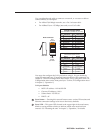
DVI-D OUTPUT
DVI connector