


Trigger Mode [TRIGGER]
Reference
DTXTREME III Owner’s Manual
109
Drum Kit mode
Reference
Song modeClick modeTr igger modeFile modeUtility modeChain modeSampling mode
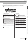
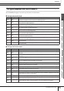
Selecting the Trigger Setup [F1] SELECT
Explanations about this display is described in the Quick Guide section on page 26.
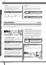
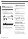
Selecting the Pad Type [F2] TYPE
From this display, you can set the type of pad or drum trigger connected to the Trigger Input jack. Make sure to select the
appropriate type matching to the particular pad or drum trigger, in order to use it at its full potential.
1
INPUT (Trigger Input jack)
Determines a target Trigger Input jack. You can select the
Trigger Input jack by hitting the desired pad when Input Lock
(page 79) is turned off (when the L indicator is not shown at
the right top of the LCD display).
B Pad Type
Determines the pad type for the Trigger Input jack specified at
1. The list below shows the pad types that can be set for the
connected pads or drum triggers.
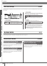
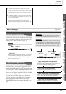
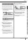
Trigger Sensitivity Settings [F3] SENS
From this display, you can set the sensitivity-related parameters, which determine how the DTXTREME III responds to the
Trigger Signals received via the Trigger Input jacks. In other words, the parameters here determine how the level of the Trig-
ger Signal (strength of your hits) is converted to the velocity recognized by the tone generator block. Keep in mind that the
level and velocity generated by hitting a pad are shown at the top of the LCD display in real time.
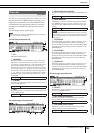
1 INPUT (Trigger Input jack)
Determines a target Trigger Input jack. You can select the
Trigger Input jack by hitting the desired pad when Input Lock
(page 79) is turned off (when the L indicator is not shown at
the right top of the LCD display).
B Gain
Determines the gain with which the DTXTREME III receives
the Trigger Signal from the pad. The higher the value, the
more easily you can get sound even when hitting the pad
softly.
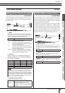
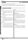
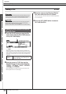
NOTE
•Keep in mind that each number in the display corresponds to the number of the Trigger Input jack printed at the top of the front
panel. Above each number, the status of the Trigger Signal received from the pad is shown in real time.
Settings snare – pad15
1
2
Settings
KP125, KP65, TP120SD/100 (for snare),
TP120SD/100 (for tom), TP65S (for snare),
TP65S (for tom), TP65, PCY155, PCY135,
PCY150S, PCY130SC, PCY130S/130,
PCY65S/65, RHH135, RHH130, DT10/20
(for snare), DT10/20 (for HiTom), DT10/20
(for LoTom), DT10/20 (for Kick), TRG Snare,
TRG HiTom, TRG LoTom, TRG Kick
5
1
234
Settings snare – pad15
Range 0 – 63