


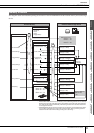

Drum Kit Mode [DRUM KIT]
Reference
DTXTREME III Owner’s Manual
81
Drum Kit mode
Reference
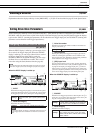
Song modeClick modeTr igger modeFile modeUtility modeChain modeSampling mode
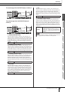
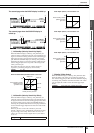
The second page when the INPUT display is called up:
The second page when the SOURCE display is
called up:
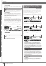
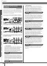
D
RevSend (Reverb Send)
When the INPUT display is called up, this parameter (for
which the value is indicated in the knob icon) determines the
Reverb Send level of each selected Trigger Input Jack. When
the SOURCE display is called up, this parameter determines
the Reverb Send level of each selected Trigger Input Source.
E
ChoSend (Chorus Send)
When the INPUT display is called up, this parameter (for
which the value is indicated in the knob icon) determines the
Chorus Send level of each selected Trigger Input Jack. When
the SOURCE display is called up, this parameter determines
the Chorus Send level of each selected Trigger Input Source.
F
VarSend (Variation Send)
When the INPUT display is called up, this parameter (for
which the value is indicated in the knob icon) determines the
Variation Send level of each selected Trigger Input Jack.
When the SOURCE display is called up, this parameter deter-
mines the Variation Send level of each selected Trigger Input
Source.
G
Dry Level
When the INPUT display is called up, this parameter (for
which the value is indicated in the knob icon) determines the
unprocessed (dry) level of the Reverb/Chorus effects’ signal
for each selected Trigger Input Jack. When the SOURCE dis-
play is called up, this parameter determines the unprocessed
(dry) level of the Reverb/Chorus effects’ signal for each
selected Trigger Input Source.
H Pan
When the INPUT display is called up, this parameter (for
which the value is indicated in the knob icon) determines the
pan (stereo) position of each selected Trigger Input Jack.
When the SOURCE display is called up, this parameter deter-
mines the pan (stereo) position of each selected Trigger Input
Source.
I OutputSel (Output Select)
When the INPUT display is called up, this parameter (for
which the value is indicated in the knob icon) determines the
Output jack of each selected Trigger Input Jack will be trans-
mitted to the external device. When the SOURCE display is
called up, this parameter determines the Output jack of each
selected Trigger Input Source will be transmitted to the exter-
nal device.
Range 0 – 127
Range 0 – 127
Range 0 – 127
Range 0 – 127
4 8567 9
4 8567 9
Range L63 – C – R63
Settings
L&R+ph (OUTPUT and PHONES), ind1&2 –
ind5&6 (INDIVIDUAL OUTPUT 1 and 2 – 5
and 6), ind1 – ind6 (one of the INDIVIDUAL
OUTPUTs), dryL&R (OUTPUT, Effect is not
applied.)
NOTE
• In the INPUT display, an asterisk (*) will appear when the value set at
each Trigger Input source is different from this parameter.