


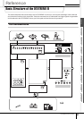

Basic Structure of the DTXTREME III
Reference
58
DTXTREME III Owner’s Manual
Reference
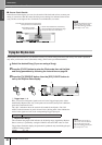
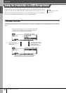
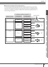
Drum Kit mode Song mode Click mode Trigger mode File mode Utility mode Chain mode Sampling mode
Pads (Trigger Input Sources) and Trigger Signals
Hitting the pad produces a trigger signal which includes information about how strongly you hit the pad and what section of
the pad you hit. The signal is transmitted via the cable and Trigger Input jack (pages 12 and 60) to the DTXTREME III. The
corresponding drum sound is triggered in the Tone Generator Block by this trigger signal. One trigger signal triggers one
Drum Voice when setting the pad to sound only a single sound at a time. One pad generates one type of trigger signal or mul-
tiple types of trigger signals according to the pad model, what section of the pad you hit, how you play the pad and the par-
ticular pad settings. The pad generating the trigger signal may be also referred to as “Trigger Input Source.”
■
Mono pads generating one type of trigger signal
Mono pads such as the TP65 drum pad and PCY65 cymbal pad can generate and transmit only one type
of the trigger signal to the DTXTREME III regardless of where on the pad you hit.
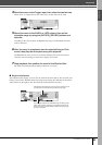
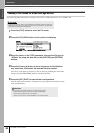
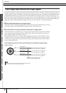
■ 2-zone pads/3-zone pads generating multiple types of trigger signal
The PCY65S generates two different types of trigger signals and the PCY155 generates three different
types of trigger signals depending on where you hit the pad, while the PCY65 generates one type of
trigger signal regardless of the location of the hit.
Pads generating multiple types of trigger signals depending on where they are hit commonly come in
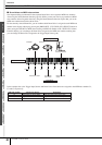
two different types: 2-zone pads or 3-zone pads. The PCY155 illustrated below as example can gener-
ate three types of trigger signals from the Pad section, Edge section and Cup section, each of which is a
separate Trigger Input Source.
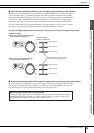
Three Trigger Input Sources on the cymbal pad and the corresponding trigger signals
NOTE
• The KICK jack is a mono jack and cannot handle multiple trigger signals
even when a 2-zone pad or 3-zone pad is connected.
The Voice assigned to the Trigger Input
Source A (Bow section) is triggered.
The Voice assigned to the Trigger Input
Source B (Edge section) is triggered.
The Voice assigned to the Trigger Input
Source C (Cup section) is triggered.
One cable and One Trigger Input jack
handle three types of trigger signals.
Tr igger Signal A
Tr igger Signal B
Tr igger Signal C
Example: PCY155
A:
Bow section
B:
Edge section
C:
Cup section