


Trigger Mode [TRIGGER]
Reference
110
DTXTREME III Owner’s Manual
Reference
Drum Kit mode Song mode Click mode Tr igger mode File mode Utility mode Chain mode Sampling mode
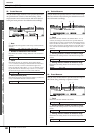
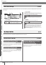
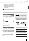
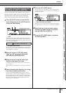
C Curve
Determines how the actual velocity will be generated and
transmitted according to the level (strength) with which you
hit the pad. The “loud2” curve, for example, provides
increased response, especially for lower velocities. The
“hard2” curve, for example, effectively lessens the overall
response compared to the other curves.
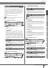
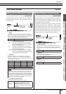
D LEVEL
Determines the level range within which the velocity is
changed.
If the Trigger Signal is below the minimum level set here, no
sound is produced. Even if the Trigger Signal exceeds the
maximum level, the sound is produced with the maximum
velocity and no greater.
E VEL (Velocity)
Determines the velocity range within which the Voice sound
is produced.
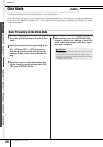
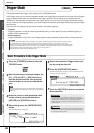
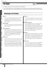
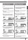
Setting the Rejection [F4] REJECT
From this display, you can set the Rejection-related parameters, letting you prevent “false hits”—such as double triggering
caused by stick rebounds, and crosstalk cause by pad vibration. The Trigger Signals regarded as “false hits” will be ignored
by proper setting of the Rejection parameters.
1 INPUT (Trigger Input jack)
Determines a target Trigger Input jack. You can select the
Trigger Input jack by hitting the desired pad when Input Lock
(page 79) is turned off (when the L indicator is not shown at
the right top of the LCD display).
B Reject Time
Determines the amount of time within which the current Trig-
ger Input jack will not accept new Trigger Signals from the
moment receiving the previous Trigger Signal. The setting
here prevents unexpected sounds generated via double trig-
gering.
C Reject Level From ALL
Determines the minimum level of the Trigger Signals (gener-
ated by hitting any other pads) which the current Trigger
Input jack will accept. In other words, the current Trigger
Input jack will not accept Trigger Signals (generated by hit-
ting any other pads) having a level lower than that specified
here. The higher the value, the less unexpected sounds are
generated via crosstalk.
D Reject Level From ***
Determines the specific Trigger Input jack and the minimum
level of the Trigger Signals (generated by hitting the pad cor-
responding to the Trigger Input jack specified here) which the
current Trigger Input jack will accept. In other words, the cur-
rent Trigger Input jack will not accept Trigger Signals (gener-
ated by hitting the pad corresponding to the Trigger Input jack
specified here) having a level lower than that specified here.
The higher the value, the less unexpected sounds are gener-
ated by crosstalk between the pad corresponding to the cur-
rent Trigger Input jack and the pad corresponding to the
Trigger Input jack specified here.
Settings loud2, loud1, normal, hard1, hard2
loud2
Velocity →
Level (Strength of your pad hitting) →
loud1 norm hard1 hard2
Range
minimum level: 0% – 99%,
maximum level: 1% – 100%
Range
minimum velocity: 0 – 126,
maximum velocity: 1 – 127
Settings snare – pad15
Range 4ms – 500ms
Range 0% – 99%
1 3
4
2
Range 0% – 99%
Settings
snare, tom1-4, ride, crash1-2, hihat, kick,
pad11-15, tom1&2, tom1&3, tom2&3,
tom2&4, tom3&4, tom2&3&4, tom all, cym all
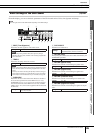
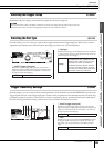
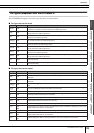
Setting example for preventing Crosstalk
When the Crash1 sound is triggered even though
only TOM1 is hit:
1. Set INPUT to “crash1,” set Reject Level From *** to “tom1,”
then turn Input Lock (page 79) to on by pressing the [SF6] but-
ton.
1
Input Lock
4