


Setting Up
26
DTXTREME III Owner’s Manual
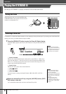
Selecting the Trigger Setup
The Trigger Setup contains various settings related to Trigger Input Signals received from pads or drum triggers (Yamaha
DT20, etc.) that are connected to the Trigger Input jacks. These settings let you optimize the DTXTREME III for best oper-
ation and response to these signals.
Select an appropriate Trigger Setup for your Drum Kit from the pre-programmed Trigger Setups in the DTXTREME III. Use
the operation described below to select the Trigger Setup you want to use.
1
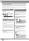
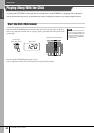
Press the [TRIGGER] button to enter the
Trigger mode.
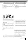
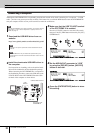
The Trigger selection display appears.
1 Trigger Setup number
Indicates the current Trigger Setup number.
B Trigger Input Level Indicator
As soon as you strike the pad, the Trigger Input Level is
shown as a bar graph above the number corresponding
to the Trigger Input jack connected to the pad you’ve
hit.
C [SF6] Input Lock
Pressing this button turns the Input Lock (“L” indicator
at the right corner of the display) on or off. Normally,
the Trigger Input jack or Trigger Input Source to be
edited can be determined by hitting the corresponding
pad. If you want to maintain it even if you hit one of the
pads, press this button to turn the Input Lock (“L” indi-
cator) on.
2
Select the desired Trigger Setup number
by using the data dial, [INC/YES] button or
[DEC/NO] button.
For information about each Trigger Setup, refer to the
Trigger Setup List on page 27.
If you want a particular Trigger Setup (i.e., the one you’ve
selected above) to be called up every time the power of the
DTXTREME III is turned on, follow the instructions below.
1
Press the [UTILITY] button to enter the
Utility mode.
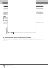
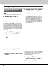
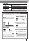
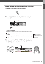
2
Press the [F1] GENERAL button followed by
the [SF4] START UP button to call up the
Start Up display.
1 TriggerNo (Trigger Setup number)
Indicates the Trigger Setup number called up when the
power of the DTXTREME III is turned on.
3
Move the cursor to the Trigger Setup num-
ber, then select the desired number by
using the data dial, [INC/YES] button or
[DEC/NO] button.
For information about each Trigger Setup, refer to the
Trigger Setup List on page 27.
4
Press the [ENTER/STORE] button to store
the setting.
Selecting the Trigger Setup
Settings PRE: 01 – PRE: 07, USR: 01 – USR: 05
2
1
3
Setting a Default Trigger Setup to be
Called Up When the Power is Turned On
NOTE
•You can create your original Trigger Setup by editing various parame-
ters. For details, see page 108.
•For Factory Set operations that take longer to process, a message
“Please keep power on…” appears during processing. While such
a message is shown (while data is being written to Flash ROM),
never attempt to turn off the power. Turning the power off in this
state results in loss of all user data and may cause the system to
freeze (due to corruption of data in the Flash ROM). This may
cause the instrument to not start up properly, even when turning
the power on next time.
1
CAUTION