


DTXTREME III Owner’s Manual
147
Appendix
Appendix
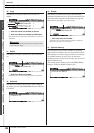
Optional DIMM Installation
This section explains how to install DIMM memory modules to the DTXTREME III.
The DTXTREME III does not necessarily support all com-
mercially available DIMMs. Yamaha cannot guarantee
operation of DIMMs that you purchase.
Before purchasing DIMMs, please consult your Yamaha
dealer, or an authorized Yamaha distributor (see list at end
of the Owner’s Manual) for advice, or visit the following
website:
http://www.yamahasynth.com/products/dtxtreme3/
•Yamaha recommends that you purchase DIMMs that
conform to the JEDEC* standard. Please be aware, how-
ever, that conformance to this standard does not consti-
tute a guarantee that the DIMMs will operate correctly
on the DTXTREME III.
* JEDEC (Joint Electron Device Engineering Council)
sets standards for terminal configurations within elec-
tronic devices.
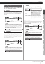
• Use only 168-pin DIMMs of 64, 128 or 256 MB capac-
ity (synchronized DRAM; PC100 or PC133).
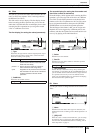
•When installing DIMMs, make sure to install them in a
matched pair of the same capacity. You cannot install
only one module and leave the second memory socket
open. Also make sure each DIMM in the pair is of the
same manufacturer and the same type. DIMMs of differ-
ent makers and configurations may not work together.
•When purchasing DIMMs, make sure that the DIMM
design does not utilize more than 18 memory chips per
module. (DIMMs comprised of more than 18 chips do
not operate correctly on the DTXTREME III.)
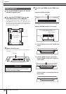
Installation Precautions
• Before beginning installation, switch off the power to the instrument and
connected peripherals, and unplug them from the power outlet. Installa-
tion or removal of any devices should be started ONLY after the instru-
ment (and the optional hardware) returns to normal room temperature.
Then remove all cables connecting the instrument to other devices.
(Leaving the power cord connected while working can result in electric
shock. Leaving other cables connected can interfere with work.)
• Be careful not to drop any screws inside the instrument during installa-
tion. (This can be prevented by keeping the optional units and cover
away from the instrument while attaching). If this does happen, be sure
to remove the screw(s) from inside the unit before turning the power on.
Loose screws inside the instrument can cause improper operation or
serious damage. If you are unable to retrieve a dropped screw, consult
your Yamaha dealer for advice.
• Install the optional units carefully as described in the procedure below.
Improper installation can cause shorts which may result in irreparable
damage and pose a fire hazard.
• Do not disassemble, modify, or apply excessive force to board areas
and connectors on optional units. Bending or tampering with boards
and connectors may lead to electric shock, fire, or equipment failures.
• It is recommended that you wear gloves to protect your hands from
metallic projections on optional units and other components. Touching
leads or connectors with bare hands may cause finger cuts, and may
also result in poor electrical contact or electrostatic damage.
• Be careful of static electricity. Static electricity discharge can damage
the IC chips on the DIMM. Before you handle the optional DIMM, to
reduce the possibility of static electricity, touch unpainted metal parts or
a ground wire on the devices that are grounded.
• Handle the optical units with care. Dropping or subjecting them to any
kind of shock may cause damage or result in a malfunction.
• Do not touch the exposed metal parts in the circuit board. Touching
these parts may result in a faulty contact.
• Be careful not to misplace any of the screws.
• Do not use any screws other than what are installed on the instrument.
Use of incorrect screws can cause damage.
Compatible DIMMs
WARNING
CAUTION
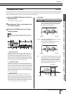
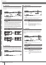
DIMM Type and DIMM Configuration
64MB x 2 = 128MB 128MB x 2 = 256MB
256MB x 2 = 512MB