


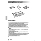
Installing Optional Hardware
Installing Optional Hardware
Reference 183
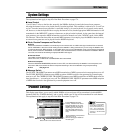
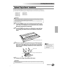
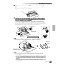
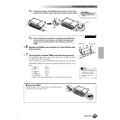
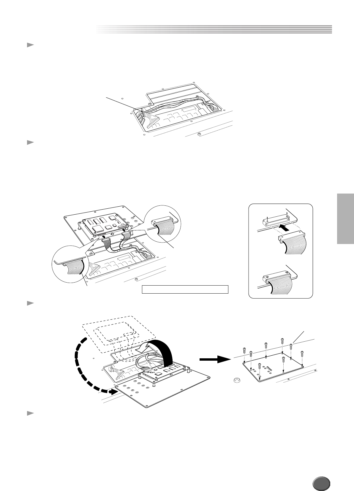
8 Unfasten the cable inside the 9000Pro as shown in the following illus-
tration.
There are three cables available for installation. The two smaller cables are used for the
Plug-in Boards; the larger cable is for the hard disk.
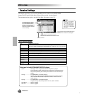
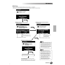
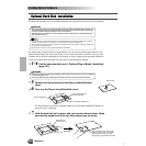
9 Carefully plug the cable connector into the Plug-in board connector
until the two notches on the cable connector lock into the sockets on
the board as shown in the illustration.
The two cables can be used interchangeably. The cable that is used determines the slot
number used by the 9000Pro. The cable with the single orange cord corresponds to Slot 1.
The cable with the yellow cord corresponds to Slot 2. Keep in mind that the slot number is
determined by the cable, not the actual installation position of the board.
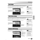
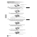
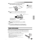
10 Attach the Plug-in board/Hard disk cover to the 9000Pro.
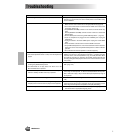
11 Check that the installed Plug-in board is functioning properly.
Turn on the power.
• A message appears indicating that the installed Plug-in Board is being initialized. The main display
then appears, indicating that the board has been successfully installed.
• If an error message appears, the 9000Pro freezes after a while, indicating that the installation was
not successful. If this happens, turn off the power and carefully go through the installation proce-
dure again.
• If you cannot select a Plug-in Voice even though no error message appears, the board has proba-
bly not been connected. If this happens, turn off the power and make sure that the Plug-in Board is
securely connected.
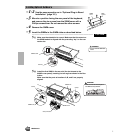
Cable clip
First board
Orange or yellow
Second board
Yellow or orange
Colored side of cable faces inward.
Black screws
Bring the cover back
around as shown, so that
the board fits in properly.
181