


Installing Optional Hardware
Installing Optional Hardware
Reference 187
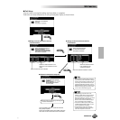
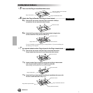
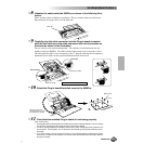
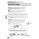
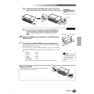
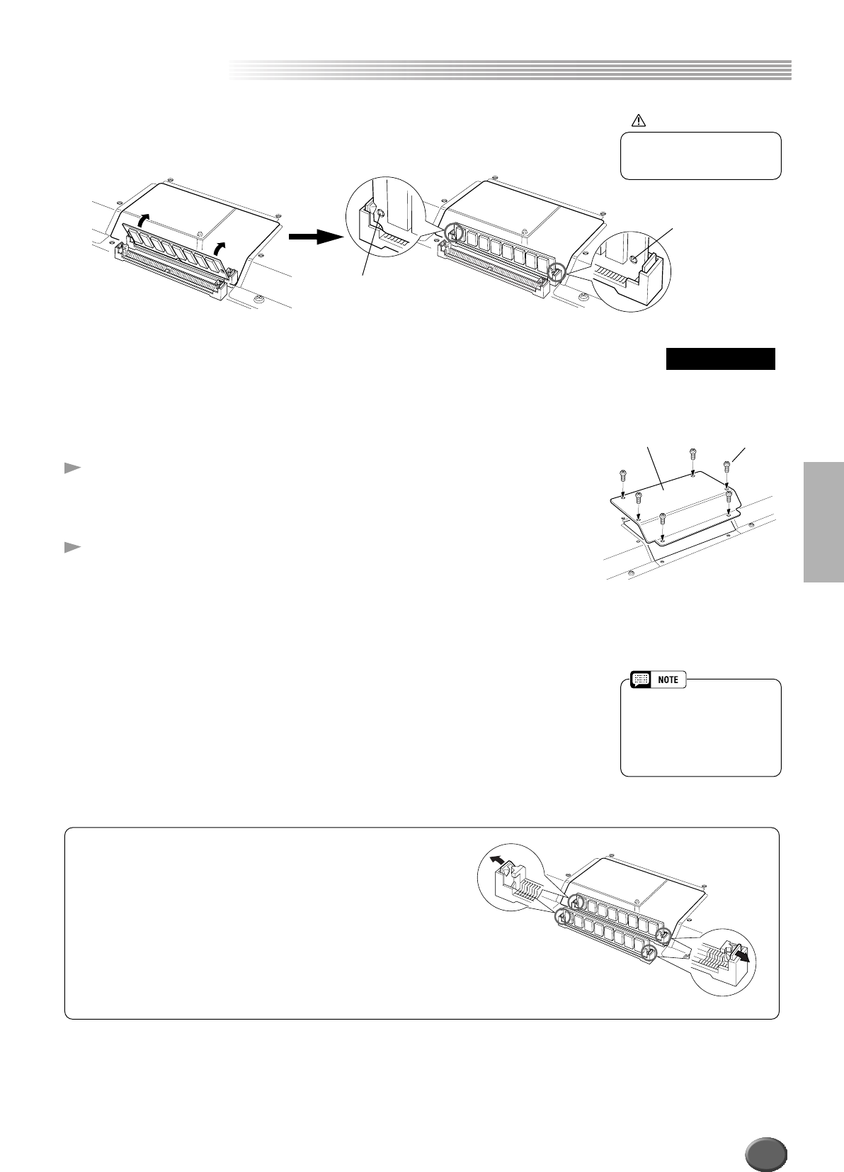
5-[3] Holding both edges of the SIMM module, raise it to the vertical
position until it firmly locks in place with the left and right clamps.
....................................................................................................................
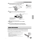
5-[4] After confirming the orientation, insert the second SIMM into
the front slot (the slot closest to the 9000Pro keyboard), and
raise it to the vertical position in the same way as the first
SIMM.
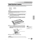
6 Replace the SIMM cover and attach it to the 9000Pro with
the six screws.
7 Check that the installed SIMMs are functioning properly.
Set the 9000Pro right-side up, and connect the power cord to the rear-panel
AC INLET jack and an AC outlet.
Turn on the power, go to the SAMPLING display (page 41), and check that
the REMAIN TIME value matches the amount of installed memory, as fol-
lows:
• 4MB x 2 106.9s
• 8MB x 2 202.1s
• 16MB x 2 392.3s
• 32MB x 2 772.7s
• No SIMMS 11.8s
(These values apply when there is no data in the wave memory.)
Clamp
Clamp
CAUTION
• Make sure that the entire
length of the SIMM is evenly
inserted.
Second SIMM
Black screwsSIMM cover
• Although the wave memory of
the 9000Pro can be expanded
to 65 megabytes, the maxi-
mum size of a single sample
recording is 32 mega bytes
(380 sec.).
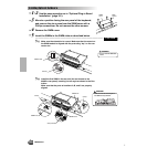
■ Removing SIMMs
SIMM modules can be removed after opening the clamps
at both ends of the connector slot.
185