


Chapter 4: Andromeda A6 Overview
ANDROMEDA A6 REFERENCE MANUAL 99
(AMP)) of the sound wave, an Envelope can also be routed to a VCO for pitch changes.
For this purpose,
ENV 1 is routed to the frequency of OSC 2. via a rotary front-panel
control; it can also be routed to
OSC 1.
The Tracking Generator, found on the A6’s front panel under the PROCESS label and
as a MOD source in many display windows, is a circuit that is used to “reshape” a
modulation source. A good example of this is using the Track Gen to reshape the
keyboard control. The A6 uses a standard equally-tempered keyboard, but its
linearity – a term that refers to how its musical intervals are even from octave to
octave and resemble “straight line”– can be significantly changed by the Track Gen
such that all five octaves can be squeezed, expanded or even inverted. The Track Gen
can be applied to many other modulators in order to modify their normal behavior.
Audio Mixing
The A6 provides several points in the sound path where audio levels are mixed. They
are arranged on the front panel into three function groups:
PRE FILTER MIX, POST
FILTER MIX
and VOICE MIX. The knobs in each group are used to set the level of a
particular element of the sound indicated by their labels. For example, the
FILT 1 BP
knob in POST FILTER MIX controls the level of the band pass (“BP”) output of FILTER 1.
To set levels, each knob controls the action of a VCA or Voltage Controlled Amplifier
– a circuit that provides internal signal amplification. Much like the level knobs and
faders on an audio mixer, you use a VCA’s knob to control “how much” of a
particular component of the Program. In most cases, the “how much” will be an
audio level, but not always. VCAs provide signal amplification – also known as
“amplitude level” or “more-or-less” control – to things like modulation amounts. The
ENV 1 AMNT knob on OSC 2 and the ENV 2 AMOUNT knobs in the VCFs are good
examples of this.
The
PRE FILTER MIX provides controls for blending both VCOs, the RING MOD, the
NOISE generator and the three external Audio Inputs. As the name implies, these
signal sources are mixed prior to being processed by the VCFs. On the A6’s rear
panel are 1/4” jacks labeled
FILTER AUDIO INPUTS. These three jacks are used to input
external audio signals for processing by the A6’s filters.
The
POST FILTER MIX controls the outputs of the two VCFs plus the unfiltered outputs
of the VCOs’ Sine waves and the Ring Modulator. This is the final mix that is sent to
the output section (via the VCA controlled by Envelope 3).
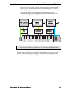
Referring to our first flowchart in Chapter 3, the
VOICE MIX is the unit’s Output
Section. Although the A6’s main mixes are set in
PRE FILTER MIX and POST FILTER MIX,
this section controls the final output levels sent to the rear panel audio out jacks. At
the bottom of the section the
LEVEL knob regulates the output of everything in the
Program currently being edited: the stereo
LEFT and RIGHT and AUX 1-2 jacks plus the
eight stereo
VOICE OUTPUTS and the stereo HEADPHONES. A switch controls whether
the output of a program will go to the Main or Aux outputs (or to neither); but a
voice is always output to its individual output as long as the
LEVEL knob is up and the
VOICE MIX switch is ON.
Last, the
MASTER VOLUME knob on the left side of the front panel controls the overall
output of the Main outs, Aux outs, and headphones, but not the individual Voice
Outs. Unlike the
LEVEL control, the position of the Volume control is not saved in
memory as part of a Program or Mix.