


Chapter 6: Modulation and Envelopes
154 ANDROMEDA A6 REFERENCE MANUAL
MOD-TG
The
MOD-TG (“modulation trigger-gate”) envelope mode is very similar in function to
the
NORM 1 mode, except that the envelope is triggered by a user selectable
modulation input instead of the keyboard.
Start: The envelope is started by an On level from the selected modulation
source.
Progress: During the Modulation Source On, the envelope proceeds normally
through Delay, Attack, Decay1, and Decay2 stages to the Sustain
stage.
Sustain: 1. If the Modulation Source On signal continues until the Sustain
stage is reached, the Modulation Source On or SUSTAIN PEDAL
ON will HOLD at the SUSTAIN Level until Modulation Input
OFF and SUSTAIN PEDAL OFF, afterwards, the envelope will
proceed to RELEASE1 and continue through to the end of the
envelope.
2. If Modulation Input OFF occurs before the SUSTAIN Stage is
reached, SUSTAIN PEDAL ON will "jump" and HOLD the
envelope in the Sustain Stage at the Current Level until SUSTAIN
PEDAL OFF, afterwards, the envelope will proceed to RELEASE1
and continue through to the end.
Gate (Release): 1. If a Modulation Input OFF (assuming Sustain Pedal is OFF) event
occurs while the envelope is in the SUSTAIN stage, the envelope
will proceed to RELEASE1 Stage and progress normally through
the envelope to the end.
2. If a Modulation Input OFF (assuming Sustain Pedal is OFF) event
occurs before the envelope reaches the SUSTAIN stage, the
envelope will "jump" immediately to the RELEASE1 stage time
(at current level) and proceed to the Release2 Level within the
time of the Release1 Stage. When the RELEASE2 stage is reached
the envelope will proceed normally through to the end.
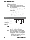
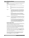
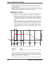
Envelope Trigger Examples
When a
MOD-TRIG or MOD-TRIG/GATE is selected in the MODE parameter, the three
Trigger and four Re-Trigger parameters become available. These parameters are used
to configure the triggering (and re-triggering) of the envelope.
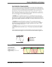
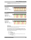
In the following seven examples, we illustrate the interaction among the trigger
SOURCE, LEVEL, and POLAR parameters. When using the Re-Trigger function, know
that these parameters are identical to their Trigger counterparts. The Re-Trigger
function contains a fourth parameter,
STAGE (Re-Trigger Stage) which simply tells
the envelope at what stage to start when re-triggered.
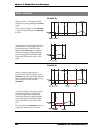
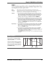
For simplicity, we’ll use a
TRIGGER/SOURCE of LFO1 for all seven examples. LFO1
will be producing a simple sine wave with a frequency of about 20Hz. We’ll also use
a
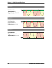
LEVEL value of +75 for the examples, with the exception of EXAMPLE 4 that assigns
a
LEVEL value of -45, just so you can see how a negative Level value affects the
point at which a trigger is generated.
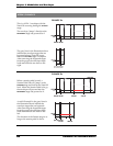
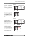
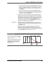
The main differences among the examples exist in the
TRIGGER/POLAR setting so
that you can see the effect of the six Polarity types. Each of the examples has a
different Polarity selected, with the exception of
EXAMPLE 4 that has a positive
polarity like
EXAMPLE 1 but has a negative Level setting.