


Chapter 6: Modulation and Envelopes
166 ANDROMEDA A6 REFERENCE MANUAL
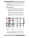
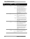
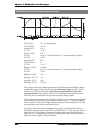
EXAMPLE 2: BI-POLAR with OFFSET plus LEVEL Changes
DELAY Time OFF (no Dela
y
sta
g
e)
ATTACK Time
4.82 S
Attack SHAPE
LOG 1
D1TIME
2.34 S
Deca
y
1 SHAPE
EXP 2
D2LEVL
Set to 79 but is effectively 60 after adjusting for Offset
D2TIME
4.50 S
Deca
y
2 SHAPE
EXP 1
SUSTAIN
Level
23
R1TIME
2.92 S
Release1 SHAPE
LINEAR
R2LEVL
Set to 72 but is effectively 50 after adjusting for Offset
R2TIME
3.92 S
Release2 SHAPE
LOG 1
Envelo
p
e OFFSET
-35
Envelo
p
e LEVEL
100
Envelo
p
e POLAR
POSWAV
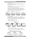
This example shows the relationship between the Offset and the envelope’s Attack
and Release2 stages. Notice that the envelope will always begin from the “0-plus-
Offset” level. Likewise, Release 2 will always end at the same level where the
envelope started. In this example, Offset is -35, shifting the envelope downward.
Thus the envelope starts below 0 and rises from there during Attack.
This example also shows how the envelope’s Level is used to increase the amplitude
of the envelope when Offset is used. Since the Offset is set to
-35 and the envelope
Level is set to
100, the Attack Stage actually reaches its maximum point at +65, and
no stages above the 0 line can exceed that value.
The stage Levels do not behave exactly as they appear in the illustration. This is
because the envelope Level is set to
100 and the Offset to -35. For example, Decay 2
Level is set to
79 (more than 3/4 between 0 and the maximum). But because it is
Offset by
-35 and amplified by 100 the the resulting level (internally calculated) is
about
60 where it appears in the illustration.