


Chapter 5: Oscillators and Filters
116 ANDROMEDA A6 REFERENCE MANUAL
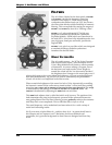
FILTERS
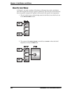
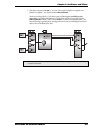
The A6’s filters, labeled on the front panel as FILTER 1
and FILTER 2, provide the harmonic control we
introduced in Chapter 3. Unlike earlier analog
synthesizers that utilized only one VCF, the A6 uses
two filters that afford excellent flexibility in harmonic
filtering. This accomplished by routing the output of
FILTER 1 into FILTER 2 so that A6 is “filtering a filter”.
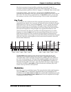
FILTER 1 is a 2-pole multi-mode VCF which was
designed to emulate the Oberheim
®
Synthesizer
Expander Module
™
(SEM) which was introduced in
the mid 1970’s. It has four fully adjustable modes: low
pass, high pass, band pass and notch, just like the
original SEM.
FILTER 2 is a 4-pole low pass filter which was designed
to emulate the Moog
®
modular synthesizers
introduced in the late 1960’s.
WHAT FILTERS DO
The A6’s audio sources – the VCOs, Noise Generator
and external audio inputs – plus the output of each
Voice’s Ring Modulator all contain a certain quantity
of harmonics. As you are editing a Program, one of
the decisions you need to make is how bright (or
muted) the sound will be. You also need to decide if
the brightness level changes as the sound plays out, if
playing high notes or low notes affects the brightness, or if you want the brightness
level to be modulated by, say, an LFO (or two) or controlled by the performance
wheels. All of this is accomplished in the filter section.
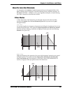
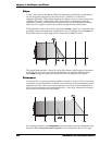
Filters control the brightness of the sound (or lack of it) by electronically controlling
the harmonic content of the audio source routed to them. A filter itself does nothing
more than set a range and an amount of frequencies that pass through it. The range
is determined by the settings of the
FILT LP, FILT HP and the FILT BP knobs. The
amount is determined by adjusting the
FREQ knob on each filter.
This
FREQ knob adjusts what is called the initial cutoff frequency. The position of the
knob determines the point in the harmonic spectrum where unwanted harmonics
start getting filtered out. The filter’s filtering process gradually reduces the overtones
until they reach a zero amplitude. This is called the filter’s slope or roll-off.
The cutoff frequency can be modulated (and most often is) for a wide variety of
useful and interesting results.
We’ll cover more of what filters do – and how they do it – in greater detail later in
this Chapter and in Chapters 6 and 7. But before we discuss methods and
procedures, let’s get some background on how filters are designed and how they
work.