


Chapter 9: The A6 Modulation Matrix
200 ANDROMEDA A6 REFERENCE MANUAL
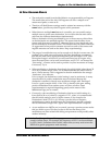
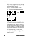
ABOUT SIGNAL FLOW IN A MOD PATH
When you’re programming a modulation, keep in mind that there are many possible
level controls between the mod source and its destination. As in a mixing console,
there are many places in the MOD signal path where the signal may be turned up,
turned down, or switched off. In the Andromeda, this flexibility allows you to do
things that are difficult or impossible on other synths.
There is no “right” way to control the levels; they simply have different
consequences depending on what you want to achieve.
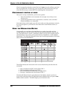
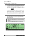
Below is a sample drawing/flow chart of the controls typical in the path from LFO 1
to Osc 1. At any one of these points, the amount of modulation can be affected.
The top part of this diagram represents the basic modulation path: LFO through
MOD
1
of Oscillator 1, aimed at its frequency. To get a basic, constant vibrato, the level of
the LFO module itself must be up, LFO 1 must be the source of MOD 1, the level of
MOD 1 must be up, MOD 1 must be enabled, and Frequency must be the mod’s
destination.
The lower blocks of the diagram show the “modulators of the modulators”: LFO 1
has its own
MOD button, which may be set to control the amplitude of the LFO itself
from any of the 79 Modulation Sources. If this is enabled (the LED next to the button
is on), the output of LFO 1 (to all destinations, not just Oscillator 1) will be affected.
Another potential level control comes from the Control Route section, which affects
how much of Mod 1 will be sent on to the frequency of the oscillator. In many
programs, the source of this route is the Mod Wheel; other programs may not enable
this route at all.
So why have two different ways of doing the same thing? What’s the difference
between controlling the level of the source and controlling the level at the
destination? The difference is that the diagram above doesn’t show the many other
possible modules that may be using LFO 1 for some purpose. It’s perfectly OK to use
LFO 1’s
MOD button to raise and lower the output level, but if you do, keep in mind
that every other
MOD in the Andromeda that may be using LFO 1 for some purpose
will be affected at the same time.
ENABLE
FREQUENCY
ENABLE
LFO 1
WAVE
/
LEVEL
MOD of LFO
DEST =
AMPLITUDE
MOD
OSC 1
MOD 1
/
LEVEL
ENABLE
CROUTE = OSC1
MOD1
LEVEL
MOD 1