


Chapter 9: The A6 Modulation Matrix
192 ANDROMEDA A6 REFERENCE MANUAL
Wheel is assigned by default to control the level of MOD 1 in each oscillator; you don’t
have to program that. In both cases, you can turn the hard-wired routes off if you
wish, but why use up a custom MOD for something that’s already there?
PERFORMANCE CONTROL OF MODS
Once you’ve set up a modulation, you have two options:
1. Have the modulation exist constantly (for example, if you always want
vibrato on) or
2. Control the modulation from a performance controller, such as the Mod
Wheel, the Ribbon, or a footswitch.
You need to know which option you will use in order to set the parameters correctly.
If you choose Option 2, you’ll need to learn about the Control Routes section, on
page 198.
USING THE MODULATION MATRIX
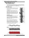
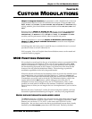
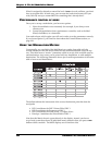
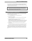
Conceptually, you can think of the Mod Matrix as a rather large table with the
sources listed down the left-hand column and the destinations listed across the top
row. This table forms a “matrix” (sometimes called an array) of the available sources
and destinations. Any source can be paired with any destination, or with multiple
destinations. The following illustration shows just a small representation of the entire
table of sources and destinations:
Env 1 Level
The bullets indicate the intersection of the source/destination pairs that form the
mod paths:
• LFO 1 modulates the OSC 2 Linear FM of OSC 1
• LFO 2 modulates the Frequency of OSC 1
• LFO 3 modulates the Level of OSC 1’s Square Wave
• Envelope 1 modulates the Pulse Width of OSC 1
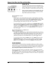
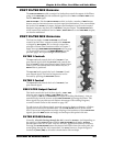
Note that this Matrix doesn’t appear directly in the display; instead, you have a
target-based system that shows an individual matrix element when you press a
MOD
button within a module. The MOD displays are all similar to this: