


Chapter 9: The A6 Modulation Matrix
194 ANDROMEDA A6 REFERENCE MANUAL
The different ways to modulate a parameter
There are four “levels” of operation that are used to control mod paths in the A6’s
Mod Matrix system:
Hardware Mods: The first level uses dedicated front panel controls to control the
level of a particular modulation source and is the most visible of the three. First level
mods such as PWM and OSC2 FM are commonly used and are easily accessed from
the front panel. Other “hardwired” mods include:
ENV 1 AMOUNT which can modulate the frequency of either or both oscillators,
PITCH WHEEL , also sending to the frequency of either or both oscillators, and
ENV 2 AMOUNT which can modulate the frequency of either or both filters.
While hardware modulators can be turned off or changed at any time, you don’t
have to use a custom mod path for these functions.
Custom Mods (Mod Matrix): Second-level mod paths are the custom paths found in
the display only after a
MOD button is pressed and are not related to a particular
source. Instead they can draw on up to 79 Mod Sources which are listed in Appendix
B. These “hidden” mod paths involve a large number of sources and destinations
that are not that common but are quite useful nonetheless. Examples include using
the parameters of a mod source as a mod destination. You can modulate an envelope
– typically a mod source – by selecting many of its parameters as destinations:
LEVEL, DELAY time, ATTACK time, DECAY 1 time, and so on. Another example would
be
EFFECTS parameters: Distortion SEND or reverb SEND.
Fixed software Mods: Third-level mod paths are also found in the display only.
These mods involve triggers that are generated by a wide variety of sources
including the keyboard, sequencer, arpeggiator and MIDI triggers. Certain other
mod sources, such as
CV IN in the Filter displays, go from a fixed source to a fixed
destination, and have no top-panel control.
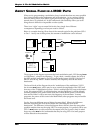
Control of Custom Mods: “Control Routes” (CROUTES) In addition, control of
certain modulation paths can be established in the background using the
CROUTES
(control routes) screen, which essentially “reaches in” to the mod path to modulate
its level from a controller or another modulation source. For example, you can
control the amount of
MOD 1 modulating Oscillator 2 from the Mod Wheel and/or the
Ribbon simultaneously. But if the Ribbon was in the mod route and the Wheel was in
the control route, the Wheel would control how much the Ribbon controlled the
modulation of VCO 2.
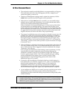
About the custom MOD paths
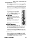
A quick look at the A6’s front panel reveals 45
MOD buttons strategically placed
around the modules. The important concept to understand here is that the function
that each
MOD button is linked to is a destination. So when you press a MOD button,
the function or module where the button is located will be the destination (“what’s
being modulated”).
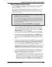
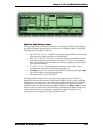
Pressing a
MOD button causes the screen to display the current mod path along with
its current values, as shown on the previous page. If a modulation has not been
assigned to this destination, the display will inform you of that (the
SOURCE will say
OFFSET ONLY). Either way, use the soft controls to edit the source and adjust the
modulation level.
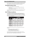
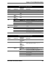
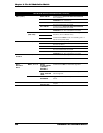
The
MOD buttons fall into two categories: those linked to a single parameter and those
linked to a particular module with several destination parameters to choose from.
The following tables will clarify this distinction: