


Chapter 10: Using Effects
ANDROMEDA A6 REFERENCE MANUAL 211
DIGITAL EFFECTS ARCHITECTURE
This section describes the 28 configuration
categories for the Digital Effects system.
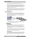
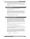
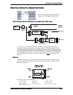
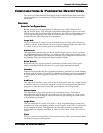
THE SIGNAL FLOW THROUGH THE EFFECTS SECTION
As you can see in the flow chart above, the effects section gets its input from the
Voice Mix Level pot. At this point, the signal is mono. This signal appears at the
SEND controls of both effects units. The Digital Effects unit can receive signal from its
own
SEND control, but even if this is all the way down, it can still receive signal from
the Analog Distortion section's output. Now that you understand where the input to
the Digital Effects comes from, let's look at what goes on inside the Digital Effects
system:
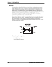
SINGLE
A Single configuration consists of one effect. These configurations utilize complex,
processor-intensive effect algorithms providing the best quality possible for each
effect type supported.
Effects that use this configuration:
Large Hall Chamber Large Plate
Hall Reverb Ambience Mono Delay
Room Reverb Plate Reverb Nonlinear Reverb
Ping Pong Delay
VCA
(ENV 3)
VOICE MIX
LEVEL
VOICE MIX
PAN
OUTPUT
AUX/MAIN
SWITCH
MAIN
DFX1
DFX2
MAIN OUT
DIGITAL
EFFECTS
SEND
OUT
ANALOG
DISTORTION
SEND
OUTPUT
MAIN OUT
P
AN/BLEND*
(in some configurations)