


Chapter 7: LFOs, S&H and Process
ANDROMEDA A6 REFERENCE MANUAL 173
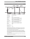
➠ DELAY Delay Time
This parameter sets time that elapses before the LFO begins its oscillation. During
this time delay, the LFO is inactive.
Range: 0 – 131.075 seconds, adjustable in increments of 2 to 10 milliseconds.
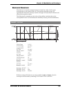
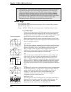
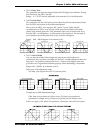
➠ PHASE Initial Phase
This parameter sets the initial phase portion where the LFO waveform starts. Here’s
how an LFO’s wave phase is described and adjusted:
One cycle of an LFO’s wave equals a 360º “phase” (cycle). Under normal
circumstances, an LFO’s wave will rise at the start of its oscillation (the initial
phase) at the neutral point of 0º. This parameter allows you to instruct the A6 to
start the LFO – its initial phase – at later points of the waveform. For example, if
you wanted to start at the peak of the wave, set this to 90 degrees.
Range: 0.00 – 360.00 degrees in increments of .01.
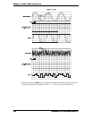
SINE WAVE
Initial Phase = 0º
0º
45º
90º
180º
270º
359º
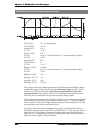
Initial Phase = 60º
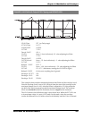
Initial Phase = 90º
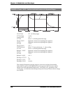
Initial Phase = 270º
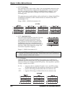
➠ PWIDTH Wave Width
You can alter the width of the triangle and pulse waves which allows for
variations in the way these waveshape rise and fall. A width adjustment alters the
duty cycle – the positive portion of the wave – relative to the negative side and
gives the wave a significantly different property when modulating a destination.
Range: 0.00 – 100.00% in increments of .01%
Pulse wave with adjustment range:
50% duty cycle (square wave) to 5% (narrow pulse)
Triangle wave width adjustment range:
100% duty cycle produces an UpSaw wave, 50% duty cycle produces a
symmetric or triangle wave, 0% duty cycle produces an DownSaw wave.
If the wave type is
SAW, below 50% produces a DownSaw, above 50% an UpSaw.