


Chapter 8: Pre Filter, Post Filter and Voice Mixes
ANDROMEDA A6 REFERENCE MANUAL 189
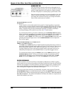
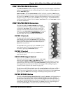
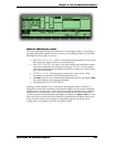
POST FILTER MIX OVERVIEW
The POST FILTER MIX module contains five knobs that control the output of the Filters
going to the
VOICE MIX plus the unfiltered signal levels of OSC 1 and OSC 2 SINE waves
and the
RING MOD signal.
POST FILTER MIX , like the PRE FILTER MIX module, includes a number of MOD buttons
that are used to route mod sources to their respective destinations. You can modulate
the levels of the
FILTER 1’s lowpass, highpass and bandpass (as well as the inverted
bandpass) outputs, and the level of
FILTER 2’s lowpass output. The PRE FILTER knob,
which controls the unfiltered levels of
OSC 1/OSC 2 SINE waves and RING MOD outputs,
can also be modulated.
POST FILTER MIX OPERATION
The first four knobs in POST FILTER MIX are all level
controls for the Filters’ outputs routed to the
VOICE MIX
as shaped by ENV 3 (AMP). We’ve already covered the
principles of these Filter functions earlier in Chapter 5
under the topics
How Filters Are Designed (refer to page
117 if you need a review) and
Signal Routing (see the
previous page). We’re providing a summary here.
FILTER 1 Controls
The FILT1 LP knob controls the level of FILTER 1’s low
pass filtered signal while the
FILT2 HP knob controls the
level of
FILTER 1’s high pass filtered signal. Both of these
knobs can be used at the same time. When they are, a
NOTCH filter is produced.
The
FILT1 BP knob controls the level of FILTER 1’s band
pass filtered signal. The band of frequencies can be
inverted by pressing the
BP INVERT button.
FILTER 2 Control
The FILT2 LP knob controls the level of FILTER 2’s low
pass filtered signal.
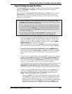
PRE FILTER Output Control
This knob controls the level of three signals – OSC 1 SINE
(the sine wave output of OSC 1), OSC 2 SINE (the sine
wave output of
OSC 2) and RING MOD (the output of the Ring Modulator) – that are
routed directly from the sources to the
POST FILTER MIX, bypassing the Filters. This
direct signal flow provides several distinct advantages when editing Programs,
covered in detail earlier in this manual on page 126.
To select any or all of these signals, press the respective button or buttons – all three
signals can be selected at the same time. Use the
PRE FILTER knob to set the initial
level. If you want independent envelope shaping of the loudness of these
PRE FILTER
signals, press the MOD button and assign an envelope at this point in the mix.
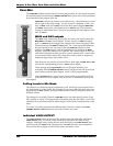
FILTER BYPASS Button
Normally, all audio flowing through the A6 is routed to FILTER 1. And depending on
the settings of the
LP INPUT button and the POST FILTER MIX level knobs, FILTER 2
becomes part of the mix as well. You can, however, bypass both Filters if necessary.
Pressing the
FILTER BYPASS button disconnects both Filters from the audio path: any
sound going through the A6 is untouched. You must, however, shape the signal’s
loudness by
ENV 3 (AMP) as all audio is hardwired to this envelope.